Tyre and Wheel System
Tyre and Wheel
HOW TO PROCEED WITH TROUBLESHOOTING
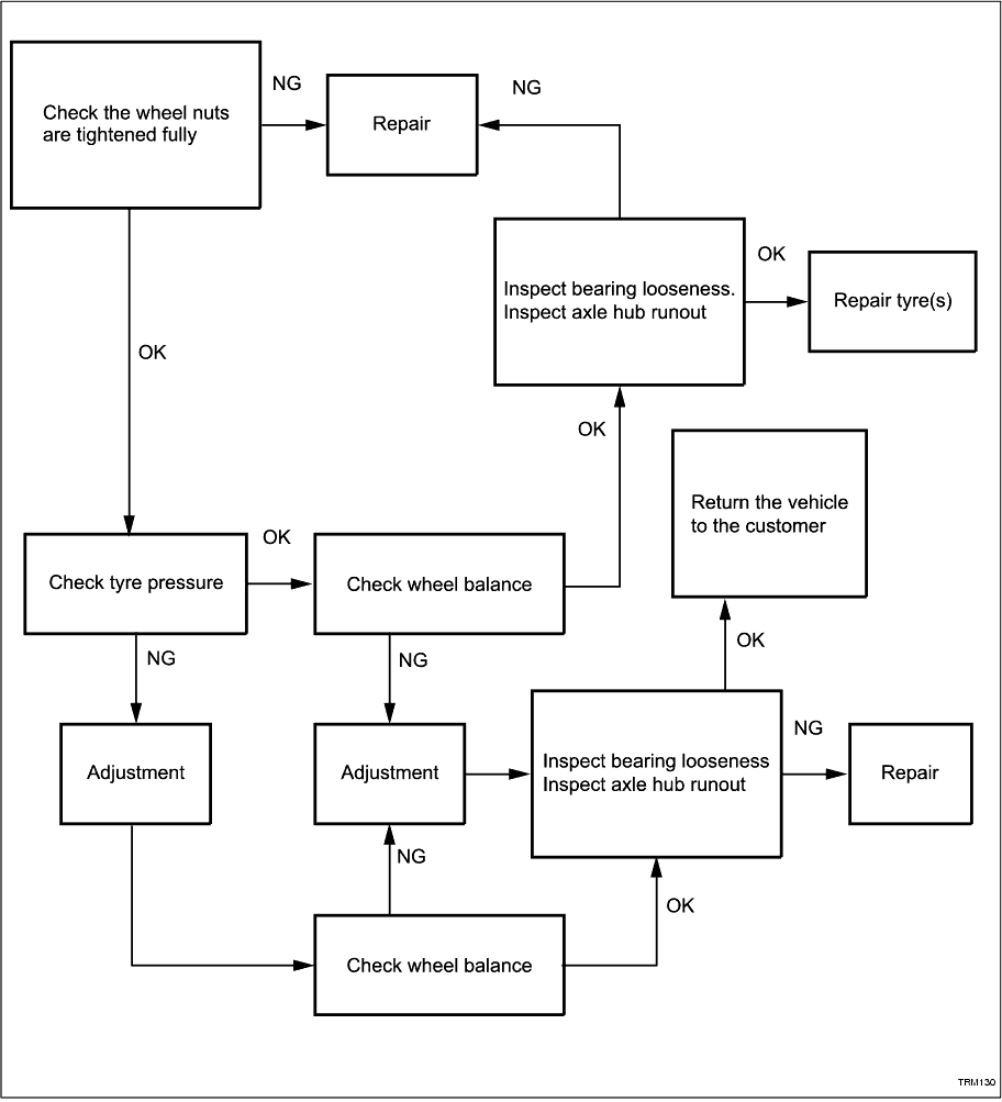
1. DIAGNOSIS OF TYRE VIBRATION
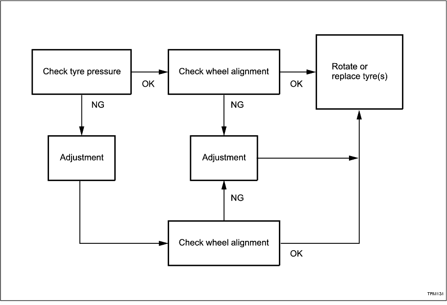
2. DIAGNOSIS OF IRREGULAR TYRE WEAR
INSPECTION
1. INSPECT TYRES
(a) Check the tyres for wear and proper inflation pressure.
*1: For driving at up to 140 km/h.
*2: For driving at over 140 km/h.
*3: Temporary use spare only.
*4: Do not exceed 80 km/h.
-
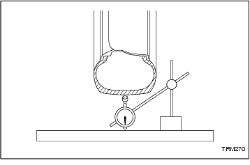
(b) Using a dial indicator, check the runout of the tyres.
Tyre runout:
1.4 mm (0.055 in.) or less
-
2. ROTATE TYRES
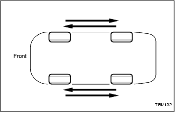
(a) Rotate the tyres as shown in the illustration.
-
3. INSPECT WHEEL BALANCE
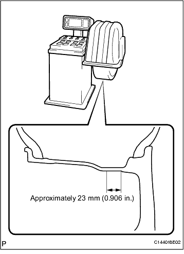
(a) Check and adjust the off-the-car balance.
Imbalance after adjustment:
8.0 g (0.018 lb.) or less
NOTICE:
• Use a cleaning detergent to remove dirt, oil, and water from the surface where the balance weight attaches.
• Do not touch the adhesive surface of the tape.
• Attach the adhesive type balance weight to the flat position shown in the illustration.
• Push the balance weight securely with a finger to adhere it to the position.
• Do not reuse the balance weight.
HINT:
• Inner side balance weight should be installed by clipping it to the rim.
• If necessary, check and adjust the on-the-car balance.
-
4. INSPECT FRONT AXLE HUB BEARING LOOSENESS
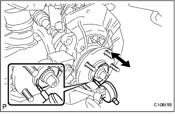
(a) Using a dial indicator, check for looseness near the centre of the axle hub.
Maximum:
0.05 mm (0.0020 in.)
NOTICE:
Ensure the dial indicator is set perpendicular to the measurement surface.
HINT:
If looseness exceeds the maximum, replace the bearing.
-
5. INSPECT REAR AXLE HUB BEARING LOOSENESS
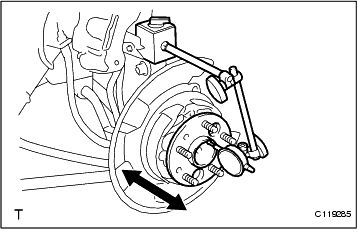
(a) Using a dial indicator, check for looseness near the centre of the axle hub.
Maximum:
0.05 mm (0.0020 in.)
NOTICE:
Ensure the dial indicator is set perpendicular to the measurement surface.
If looseness exceeds the maximum, replace the axle hub assembly.
-
6. INSPECT FRONT AXLE HUB RUNOUT
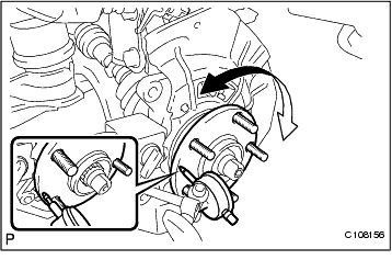
(a) Using a dial indicator, check for runout on the surface of the axle hub outside the hub bolt.
Maximum:
0.05 mm (0.0020 in.)
NOTICE:
Ensure the dial indicator is set perpendicular to the measurement surface.
HINT:
If runout exceeds the maximum, replace the axle hub.
-
7. INSPECT REAR AXLE HUB RUNOUT
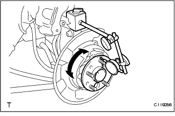
(a) Using a dial indicator, check for runout on the surface of the axle hub outside the hub bolt.
Maximum:
0.07 mm (0.0027 in.)
NOTICE:
Ensure the dial indicator is set perpendicular to the measurement surface.
If runout exceeds the maximum, replace the axle hub assembly.
-