FRONT SEAT ASSEMBLY (for Power Seat)
Seat
COMPONENTS
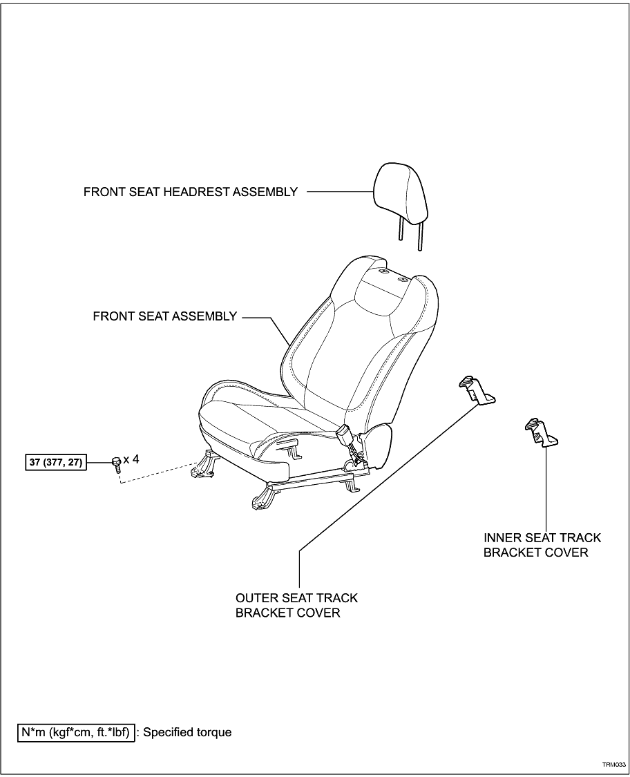
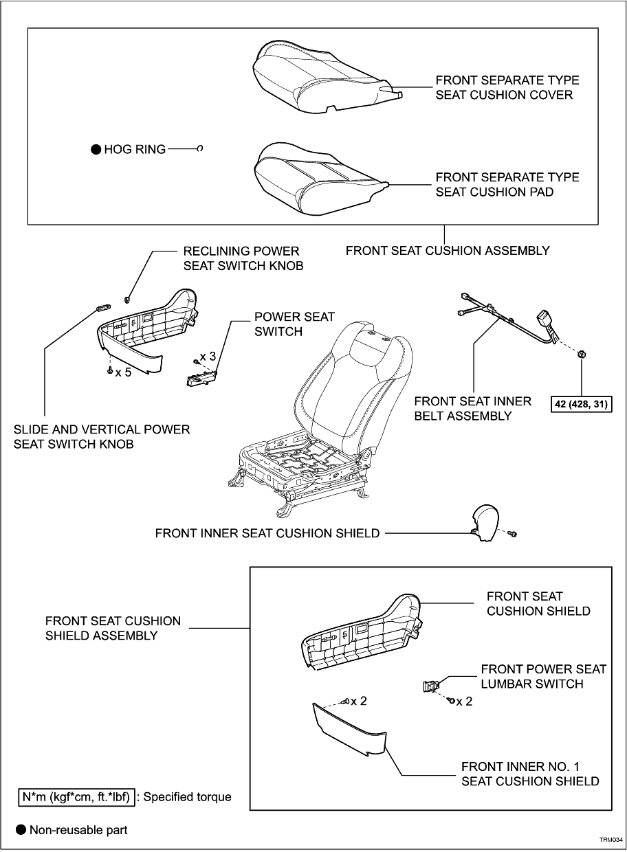
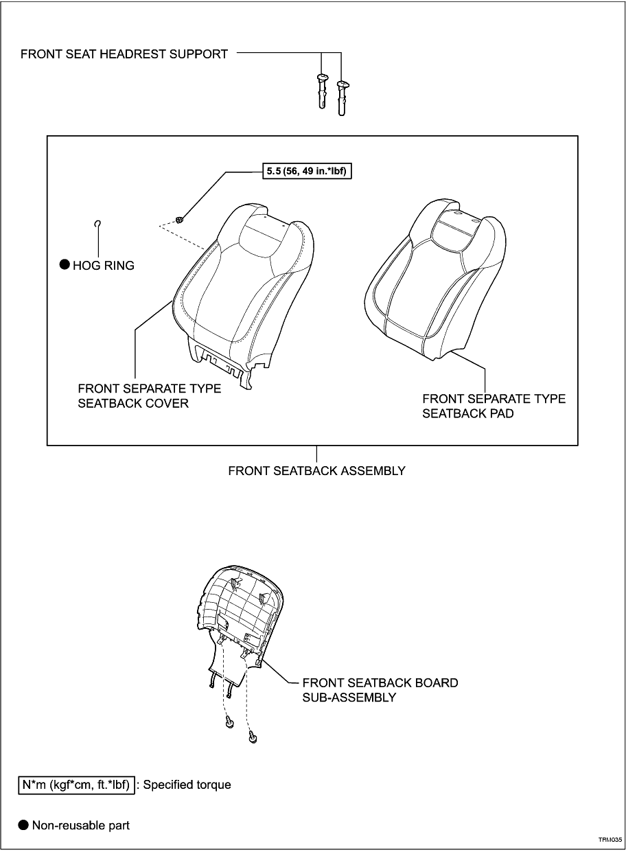
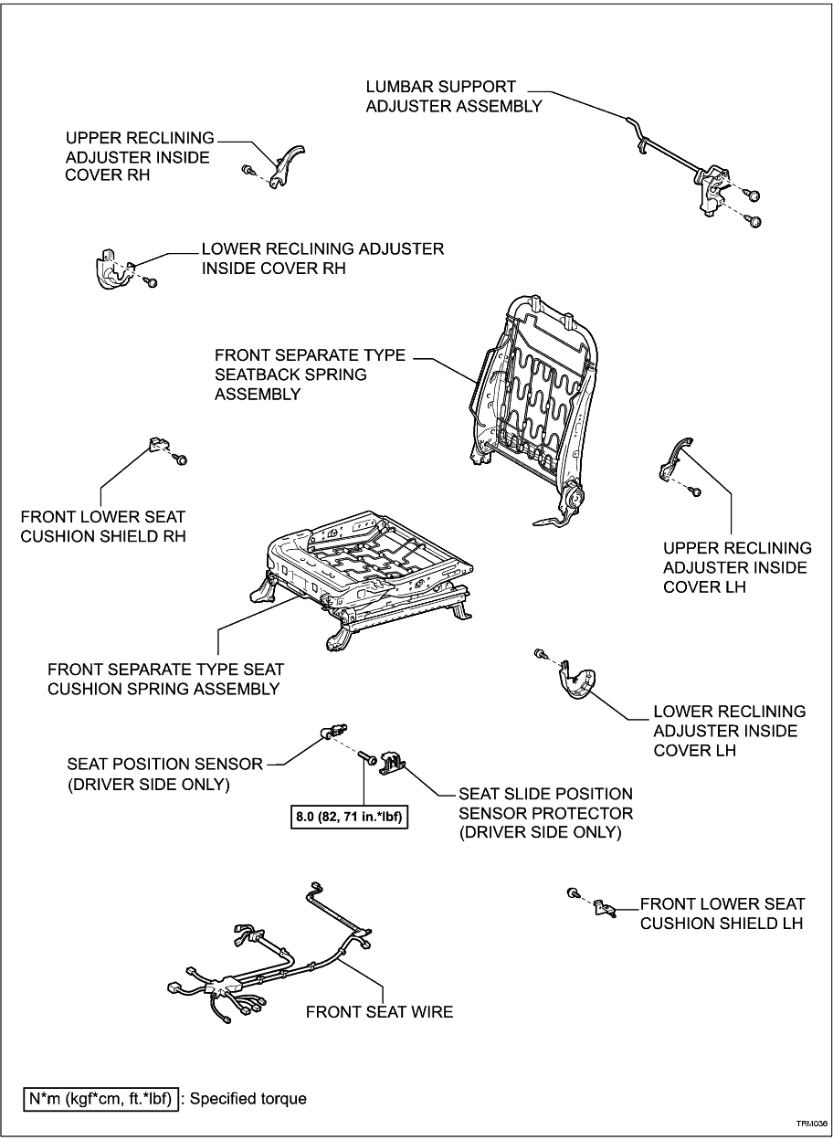
REMOVAL
1. REMOVE FRONT SEAT HEADREST ASSEMBLY
2. REMOVE OUTER SEAT TRACK BRACKET COVER
(a) Move the front seat assembly fully forward by operating the slide and vertical power seat switch knob.
-
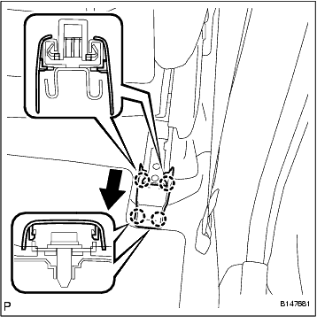
(b) Using a screwdriver, disengage the 4 claws and remove the front seat rear outer track bracket cover.
HINT:
Tape the screwdriver tip before use.
-
3. REMOVE INNER SEAT TRACK BRACKET COVER
(a) Using a screwdriver, disengage the 4 claws and remove the front seat rear inner track bracket cover.
HINT:
Tape the screwdriver tip before use.
-
4. REMOVE FRONT SEAT ASSEMBLY
(a) Operate the power seat switch knob and move the seat to the rear-most position.
-
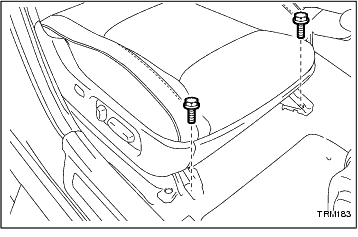
(b) Remove the 2 bolts on the front seat track bracket.
-
(c) Operate the power seat switch knob and move the seat to the position farthest forward.
-
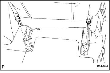
(d) Remove the 2 bolts on the rear seat track bracket.
-
(e) Disconnect the cable from the negative (-) battery terminal.
CAUTION:
Wait at least 90 seconds after disconnecting the cable from the negative (-) battery terminal to prevent the airbag and seat belt pretensioner from deploying.
-
(f) Disconnect the connectors under the seat. Then remove the front seat assembly.
-
DISASSEMBLY
CAUTION:
Wear protective gloves. Sharp areas on the seat frame and adjuster may injure your hands.
1. REMOVE RECLINING POWER SEAT SWITCH KNOB
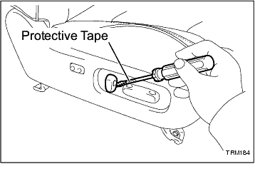
(a) Using a screwdriver, detach the reclining power seat switch knob.
HINT:
Tape the screwdriver tip before use.
-
2. REMOVE SLIDE AND VERTICAL POWER SEAT SWITCH KNOB
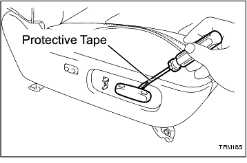
(a) Using a screwdriver, detach the slide and vertical power seat switch knob.
HINT:
Tape the screwdriver tip before use.
-
3. REMOVE FRONT SEAT CUSHION SHIELD ASSEMBLY
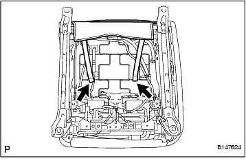
(a) Disengage the 2 hooks.
-
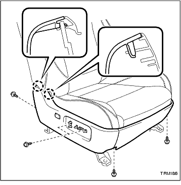
(b) Remove the 5 screws.
-
(c) Disengage the 2 claws and separate the front seat cushion shield assembly.
-
(d) Disconnect the connector from the front power seat lumbar switch.
-
4. REMOVE FRONT INNER NO. 1 SEAT CUSHION SHIELD
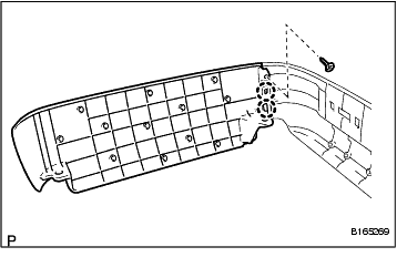
(a) Remove the screw.
-
(b) Disengage the 2 claws and remove the front inner No. 1 seat cushion shield.
-
5. REMOVE FRONT POWER SEAT LUMBAR SWITCH
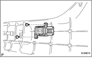
(a) Remove the 2 screws and front power seat lumbar switch.
-
6. REMOVE FRONT INNER SEAT CUSHION SHIELD
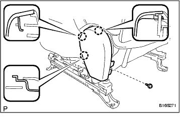
(a) Remove the screw.
-
(b) Disengage the 3 claws and remove the front inner seat cushion shield.
-
7. REMOVE FRONT SEAT INNER BELT ASSEMBLY
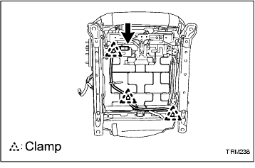
(a) Disconnect the connector and disengage the 3 clamps.
-
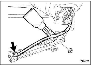
(b) Disconnect the connector.
-
(c) Remove the nut and front seat inner belt assembly.
-
8. REMOVE POWER SEAT SWITCH
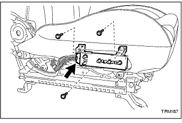
(a) Remove the 3 screws.
-
(b) Disconnect the connector and remove the power seat switch.
-
9. REMOVE FRONT SEAT CUSHION ASSEMBLY
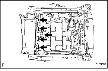
(a) Disengage the connector.
-
(b) Remove the 4 hooks.
-
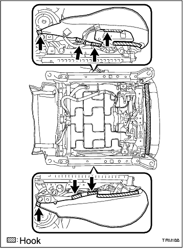
(c) Using a screwdriver, disengage the hooks and remove the front seat cushion assembly.
-
10. REMOVE FRONT SEPARATE TYPE SEAT CUSHION COVER
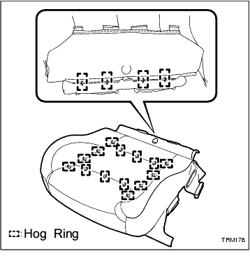
(a) Remove the 18 hog rings and front separate type seat cushion cover from the seat cushion pad.
-
11. REMOVE FRONT SEATBACK BOARD SUB-ASSEMBLY
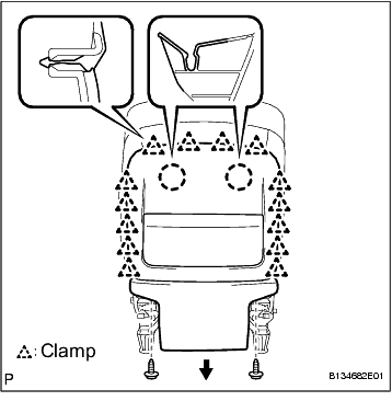
(a) Remove the 2 screws.
-
(b) Disconnect the 14 clamps and front separate type seatback cover.
-
(c) Remove in the direction of the arrow in the illustration to detach the 2 claws. Then, remove the front seatback board sub-assembly.
-
12. REMOVE FRONT SEAT HEADREST SUPPORT
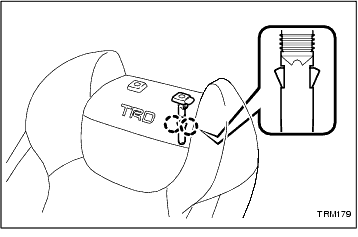
(a) Disengage the 2 claws and remove the front seat headrest support.
-
(b) Repeat for the opposite side.
-
13. REMOVE FRONT SEATBACK ASSEMBLY
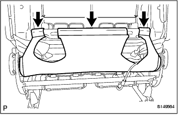
(a) Disengage the 3 hooks.
-
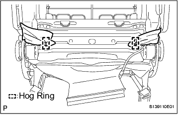
(b) Remove the 2 hog rings.
-
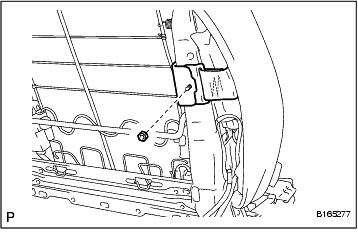
(c) Remove the nut and separate the 2 brackets.
-
(d) Remove the front seatback assembly.
-
14. REMOVE FRONT SEPARATE TYPE SEATBACK COVER
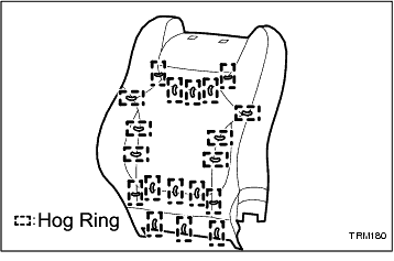
(a) Remove the 19 hog rings and front separate type seatback cover from the seatback pad.
-
15. REMOVE LUMBAR SUPPORT ADJUSTER ASSEMBLY
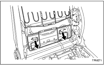
(a) Unattach the seat back spring lower mounts from the frame.
-
(b) Unhook the top of the spring and remove.
-
(c) Disconnect the connector.
-
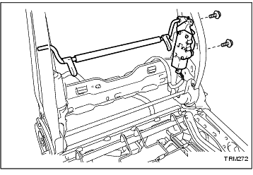
(d) Remove the 2 screws and lumbar support adjuster assembly.
-
16. REMOVE LOWER RECLINING ADJUSTER INSIDE COVER RH
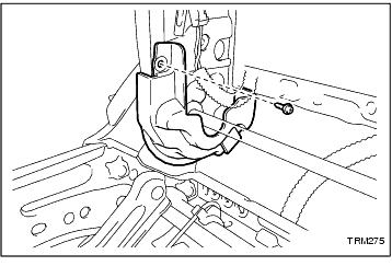
(a) Remove the screw and lower reclining adjuster inside cover RH.
-
17. REMOVE LOWER RECLINING ADJUSTER INSIDE COVER LH
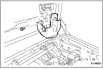
(a) Remove the screw and lower reclining adjuster inside cover LH.
-
18. REMOVE UPPER RECLINING ADJUSTER INSIDE COVER RH
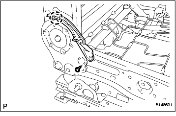
(a) Remove the screw.
-
(b) Disengage the claw and remove the upper reclining adjuster inside cover RH.
-
19. REMOVE UPPER RECLINING ADJUSTER INSIDE COVER LH
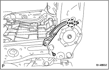
(a) Remove the screw.
-
(b) Disengage the claw and remove the upper reclining adjuster inside cover LH.
-
20. REMOVE FRONT LOWER SEAT CUSHION SHIELD LH
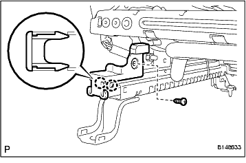
(a) Remove the screw.
-
(b) Disengage the 2 claws and remove the front lower seat cushion shield LH.
-
21. REMOVE FRONT LOWER SEAT CUSHION SHIELD RH
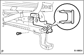
(a) Remove the screw.
-
(b) Disengage the 2 claws and remove the front lower seat cushion shield RH.
-
22. REMOVE FRONT SEPARATE TYPE SEATBACK SPRING ASSEMBLY
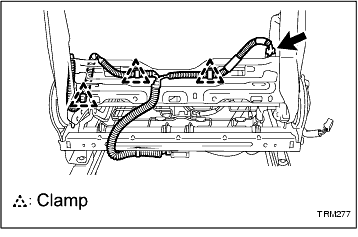
(a) Disconnect the connector and detach the 3 clamps.
-
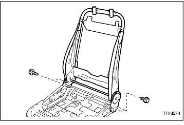
(b) Remove the 4 bolts and front separate type seat back spring assembly.
-
23. REMOVE SEAT POSITION SENSOR (for Driver Seat)
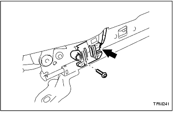
(a) Disconnect the connector.
-
(b) Using a TORX socket (T30), remove the TORX screw and seat position sensor with the seat slide position sensor protector.
-
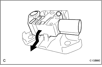
(c) Remove the seat position sensor from the seat slide position sensor protector as shown in the illustration.
-
24. REMOVE FRONT SEAT WIRE
INSPECTION
1. INSPECT FRONT SEAT FRAME WITH ADJUSTER LH
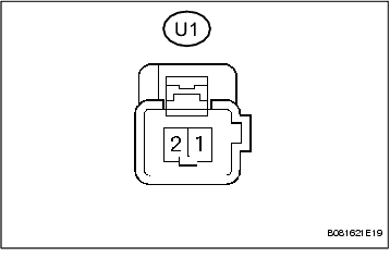
(a) Check operation of the slide motor.
-
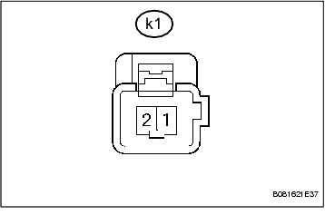
(b) Check operation of the reclining motor.
-
(c) If the result is not as specified, replace the seat frame with adjuster.
-
2. INSPECT FRONT SEAT FRAME WITH ADJUSTER RH
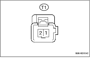
(a) Check operation of the slide motor.
-
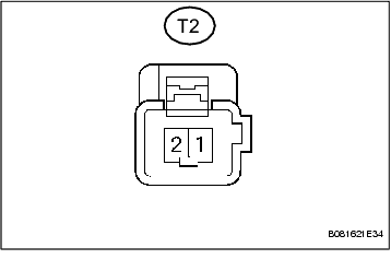
(b) Check operation of the front vertical motor.
-
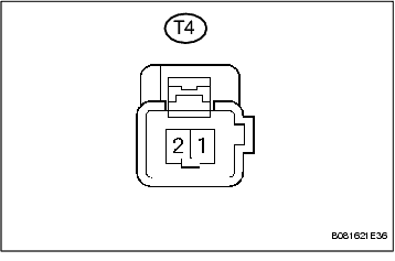
(c) Check operation of the lifter motor.
-
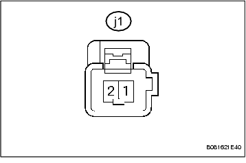
(d) Check operation of the reclining motor.
-
(e) If the result is not as specified, replace the seat frame with adjuster.
-
REASSEMBLY
CAUTION:
Wear protective gloves. Sharp areas on the seat adjuster may injure your hands.
1. INSTALL FRONT SEAT WIRE
2. INSTALL SEAT POSITION SENSOR (for Driver Seat)
(a) Check the ignition switch is off.
-
(b) Check the negative battery (-) cable is disconnected.
CAUTION:
Wait for 90 seconds after disconnecting the cable to prevent airbag deployment.
-
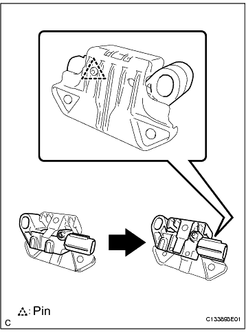
(c) Engage the pin and install the seat position sensor to the seat slide position sensor protector as shown in the illustration.
-
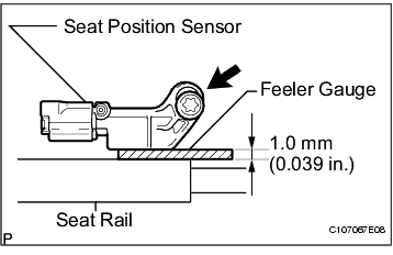
(d) Using a 1.0 mm (0.039 in.) feeler gauge, temporarily install the seat position sensor.
NOTICE:
• If the seat position sensor has been dropped, or there are any cracks, dents or other defects in the case or connector, replace the seat position sensor with a new one.
• When installing the seat position sensor, be careful the SRS wiring does not interfere with other parts and that it is not pinched between other parts.
-
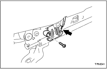
(e) Using a TORX socket (T30), tighten the TORX screw to install the seat position sensor.
Torque:
8.0 N*m
(82 kgf*cm,
71 in.*lbf)
-
(f) Ensure the clearance between the seat position sensor and the seat rail is within 0.6 mm (0.024 in.) to 2.0 mm (0.079 in.).
-
(g) Check there is no looseness in the installation parts of the seat position sensor.
-
(h) Connect the connector.
-
3. INSTALL FRONT SEPARATE TYPE SEATBACK SPRING ASSEMBLY
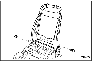
(a) Install the front separate type seatback spring assembly with the 4 bolts.
Torque:
42 N*m
(428 kgf*cm,
31 ft.*lbf)
-
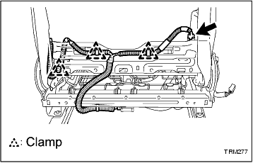
(b) Connect the 2 clamps and connector.
-
4. INSTALL FRONT LOWER SEAT CUSHION SHIELD LH
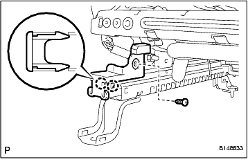
(a) Engage the 2 claws.
-
(b) Install the front lower seat cushion shield LH with the screw.
-
5. INSTALL FRONT LOWER SEAT CUSHION SHIELD RH
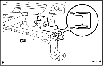
(a) Engage the 2 claws.
-
(b) Install the front lower seat cushion shield RH with the screw.
-
6. INSTALL UPPER RECLINING ADJUSTER INSIDE COVER LH
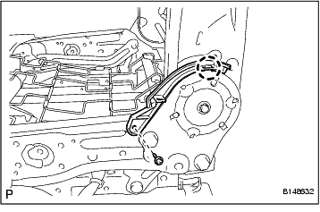
(a) Engage the claw.
-
(b) Install the upper reclining adjuster inside cover LH with the screw.
-
7. INSTALL UPPER RECLINING ADJUSTER INSIDE COVER RH
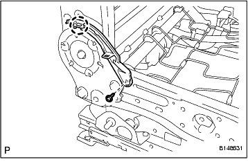
(a) Engage the claw.
-
(b) Install the upper reclining adjuster inside cover RH with the screw.
-
8. INSTALL LOWER RECLINING ADJUSTER INSIDE COVER LH
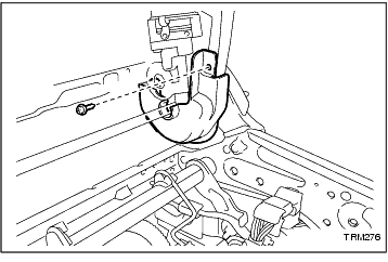
(a) Install the lower reclining adjuster inside cover LH with the screw.
-
9. INSTALL LOWER RECLINING ADJUSTER INSIDE COVER RH
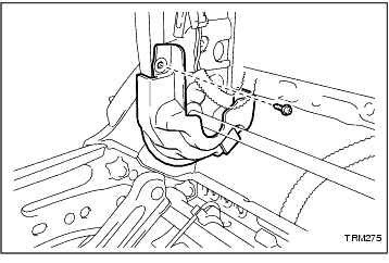
(a) Install the lower reclining adjuster inside cover RH with the screw.
-
10. INSTALL LUMBAR SUPPORT ADJUSTER ASSEMBLY
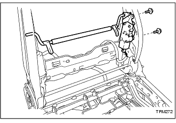
(a) Install the lumbar support adjuster assembly with the 2 screws.
-
(b) Connect the connector.
-
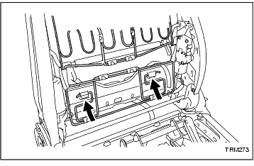
(c) Attach the top of the seat back spring to the frame.
-
(d) Attach the seat back spring lower mounts to the frame.
-
11. INSTALL FRONT SEPARATE TYPE SEATBACK COVER
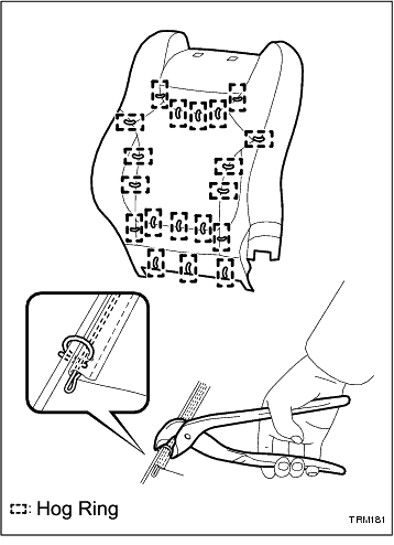
(a) Using hog ring pliers, install the front separate type seatback cover to the front seatback pad with 19 new hog rings.
NOTICE:
• Be careful not to damage the cover.
• When installing the hog rings, take care to minimise wrinkles as much as possible.
-
12. INSTALL FRONT SEATBACK ASSEMBLY
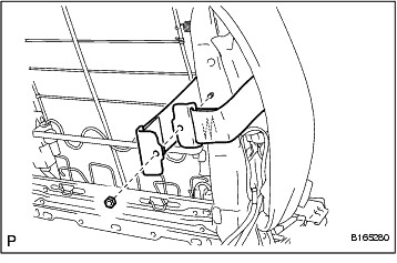
(a) Fully cover the airbag with the 2 seatback cover brackets and tighten the nut.
Torque:
5.5 N*m
(56 kgf*cm,
49 in.*lbf)
NOTICE:
• The seatback cover must be securely installed. Otherwise, the side airbags may not deploy properly.
• Ensure the strap is not twisted after installing the bracket.
• Install the bracket securely.
-
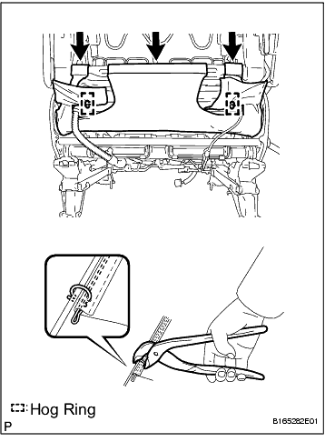
(b) Engage the 3 hooks.
-
(c) Using hog ring pliers, install 2 new hog rings.
NOTICE:
• Be careful not to damage the cover.
• When installing the hog rings, take care to minimise wrinkles as much as possible.
-
13. INSTALL FRONT SEAT HEADREST SUPPORT
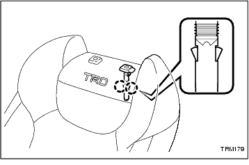
(a) Engage the 2 claws to install the front seat headrest support.
-
(b) Repeat for the opposite side.
-
14. INSTALL FRONT SEATBACK BOARD SUB-ASSEMBLY
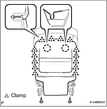
(a) Engage the 2 claws.
-
(b) Engage the 14 claws.
-
(c) Install the front seatback board sub-assembly with the 2 screws.
-
15. INSTALL FRONT SEPARATE TYPE SEAT CUSHION COVER
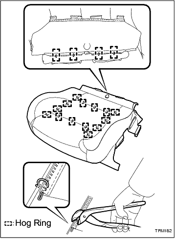
(a) Using hog ring pliers, install the front separate type seat cushion cover to the front separate type seat pad with 18 new hog rings.
NOTICE:
• Be careful not to damage the cover.
• When installing the hog rings, take care to minimise wrinkles as much as possible.
-
16. INSTALL FRONT SEAT CUSHION ASSEMBLY
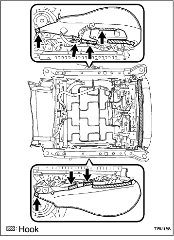
(a) Engage the hooks.
-
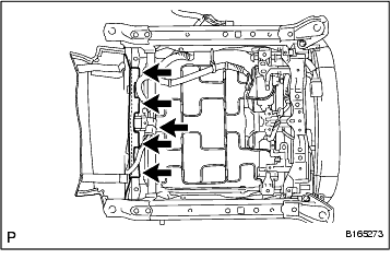
(b) Engage the 4 hooks.
-
(c) Connect the connector.
-
17. INSTALL FRONT SEAT INNER BELT ASSEMBLY
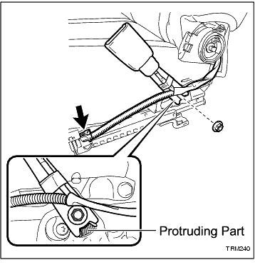
(a) Install the front seat inner belt assembly with the nut.
Torque:
42 N*m
(428 kgf*cm,
31 ft.*lbf)
NOTICE:
Do not allow the anchor part of the front seat inner belt assembly to overlap the protruding part of the front seat adjuster.
-
(b) Connect the connector.
-
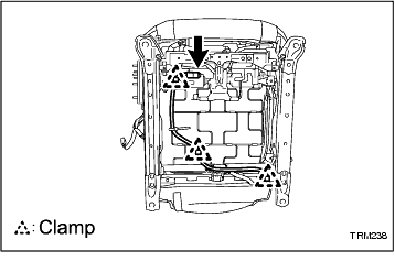
(c) Connect the connector and engage the 2 clamps.
-
18. INSTALL FRONT INNER SEAT CUSHION SHIELD
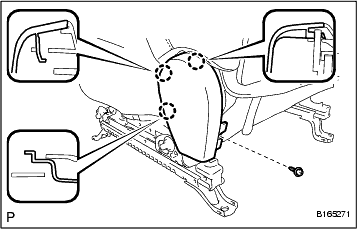
(a) Engage the 3 claws.
-
(b) Install the front inner seat cushion shield with the screw.
-
19. INSTALL POWER SEAT SWITCH
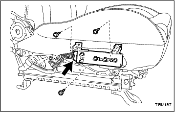
(a) Install the power seat switch with the 3 screws.
-
(b) Connect the connector.
-
20. INSTALL FRONT POWER SEAT LUMBAR SWITCH
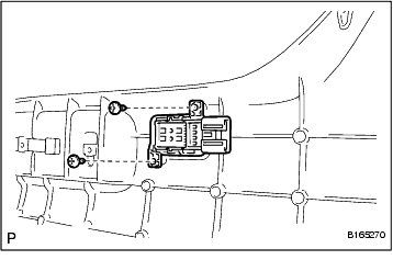
(a) Install the front power seat lumbar switch with the 2 screws.
-
21. INSTALL FRONT INNER NO. 1 SEAT CUSHION SHIELD
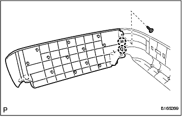
(a) Engage the 2 claws.
-
(b) Install the front inner No. 1 seat cushion shield with the 2 screws.
-
22. INSTALL FRONT SEAT CUSHION SHIELD ASSEMBLY
(a) Connect the connector.
-
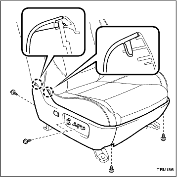
(b) Engage the 2 claws.
-
(c) Install the front seat cushion shield assembly with the 5 screws.
-
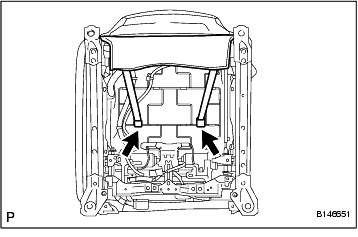
(d) Install the 2 rubber bands on the backside of the front seatback board sub-assembly.
-
23. INSTALL SLIDE AND VERTICAL POWER SEAT SWITCH KNOB
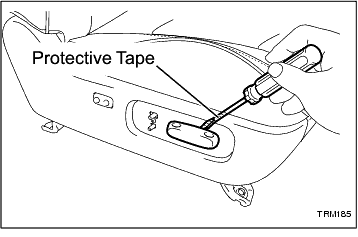
(a) Install the slide and vertical power seat switch knob.
-
24. INSTALL RECLINING POWER SEAT SWITCH KNOB
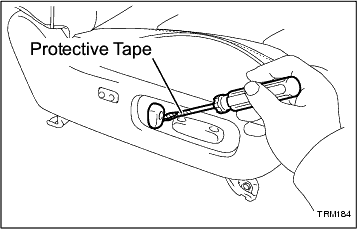
(a) Install the reclining power seat switch knob.
-
INSTALLATION
1. INSTALL FRONT SEAT ASSEMBLY
(a) Place the seat in the cabin.
-
(b) Connect the connectors under the seat.
-
(c) Connect the cable to the negative (-) battery terminal.
-
(d) Move the front seat assembly fully forward by operating the slide and vertical power seat switch knob.
NOTICE:
Check the seat is locked.
-
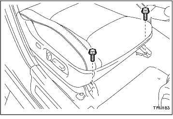
(e) Temporarily install the front seat track bracket with the 2 bolts.
-
(f) Move the front seat assembly fully forward by operating the slide and vertical power seat switch knob.
NOTICE:
Check the seat is locked.
-
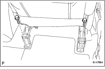
(g) Temporarily install the rear seat track bracket with the 2 bolts.
-
(h) Move the front seat assembly to the rear-most position by operating the slide and vertical power seat switch knob.
NOTICE:
Check the seat is locked.
-
(i) Fully tighten the 2 bolts on the front seat track bracket in the order of the inner bolt and then the outer bolt.
Torque:
37 N*m
(377 kgf*cm,
27 ft.*lbf)
-
(j) Move the front seat assembly fully forward by operating the slide and vertical power seat switch knob.
NOTICE:
Check the seat is locked.
-
(k) Fully tighten the 2 bolts on the rear seat track bracket in the order of the inner bolt and then the outer bolt.
Torque:
37 N*m
(377 kgf*cm,
27 ft.*lbf)
-
2. INSTALL OUTER SEAT TRACK BRACKET COVER
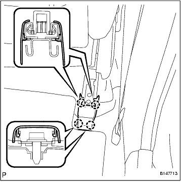
(a) Engage the 4 claws and install the front seat rear outer track bracket cover.
-
3. INSTALL INNER SEAT TRACK BRACKET COVER
(a) Engage the 4 claws and install the front seat rear inner track bracket cover.
-
4. INSTALL FRONT SEAT HEADREST ASSEMBLY
5. INSPECT SRS WARNING LIGHT
6. INSPECT FRONT SEAT ASSEMBLY
(a) Inspect the power seat operation.
-