| B |  |
| GO TO DTC CHART (Click here) |
DTC P2121 Throttle / Pedal Position Sensor / Switch "D" Circuit Range / Performance |
| DTC No. | DTC Detection Condition | Trouble Area |
| P2121 | Difference between VPA and VPA2 less than 0.4 V, or more than 1.2 V for 0.5 seconds (1 trip detection logic) |
|
| 1.CHECK ANY OTHER DTCS OUTPUT (IN ADDITION TO DTC P2121) |
Connect the intelligent tester to the DLC3.
Turn the ignition switch to ON.
Turn the tester on.
Enter the following menus: Powertrain / Engine and ECT / DTC.
Read the DTCs.
| Result | Proceed to |
| DTC P2121 is output | A |
| DTC P2121 and other DTCs are output | B |
|
| ||||
| A | |
 |
| 2.READ VALUE USING INTELLIGENT TESTER (ACCELERATOR POSITION SENSOR) |
 |
Connect the intelligent tester to the DLC3.
Turn the ignition switch to ON.
Turn the tester on.
Enter the following menus: Powertrain / Engine and ECT / Data List / All Data / Accel Sensor Out No. 1 and Accel Sensor Out No. 2.
Read the values displayed on the tester.
| Accelerator Pedal Operation | Accel Sensor Out No. 1 | Accel Sensor Out No. 2 | Difference between Accel Sensor Out No. 1 and Accel Sensor Out No. 2 |
| Released | 0.5 to 1.1 V | 1.2 to 2.0 V | 0.4 to 1.2 V |
| Fully Depressed | 2.6 to 4.5 V | 3.4 to 5.0 V |
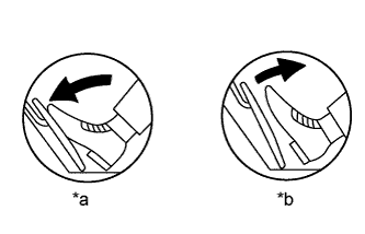
| *a | Depressed |
| *b | Released |
|
| ||||
| OK | ||
 | ||
| ||
| 3.REPLACE ACCELERATOR PEDAL SENSOR ASSEMBLY (ACCELERATOR PEDAL POSITION SENSOR) |
Replace the accelerator pedal sensor assembly (Click here).
| NEXT | |
|
| 4.CHECK WHETHER DTC OUTPUT RECURS (ACCELERATOR PEDAL POSITION SENSOR DTCS) |
Connect the intelligent tester to the DLC3.
Turn the ignition switch to ON.
Turn the tester on.
Clear the DTCs (Click here).
Start the engine.
Fully depress and release the accelerator pedal.
Check that 20 seconds or more have elapsed since the ignition switch was turned to ON.
Enter the following menus: Powertrain / Engine and ECT / DTC.
Read the DTCs.
| Result | Proceed to |
| DTC P2121 is output | A |
| DTC is not output | B |
|
| ||||
| A | ||
| ||
| ||
