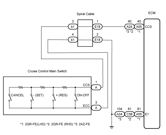
CRUISE CONTROL SYSTEM > Cruise Control Switch Circuit |
| 1.READ VALUE ON INTELLIGENT TESTER |
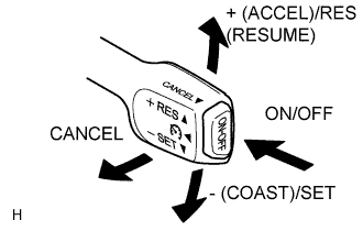 |
Connect the intelligent tester to the DLC3.
Turn the ignition switch to the ON position and turn the intelligent tester main switch on.
Check the DATA LIST for proper functioning of the cruise control main switch.
| Item | Measurement Item/Display (Range) | Normal Condition | Diagnostic Note |
| Main SW (Main) | Main switch signal (Main CPU)/ON or OFF | ON: Cruise control main switch on OFF: Cruise control main switch off | - |
| Cancel SW | CANCEL switch signal/ON or OFF | ON: CANCEL switch on OFF: CANCEL switch off | - |
| SET / COAST SW | SET / COAST switch signal/ON or OFF | ON: - (COAST)/SET switch on OFF: - (COAST)/SET switch off | - |
| RES / ACC SW | RES / ACC switch signal/ON or OFF | ON: + (ACCEL)/RES (RESUME) switch on OFF: + (ACCEL)/RES (RESUME) switch off | - |
| Main SW (Sub) | Main switch signal (Sub CPU) / ON or OFF | ON: Cruise control main switch ON OFF: Cruise control main switch OFF | - |
| Result | Proceed to |
| OK | A |
| NG (All items are defective) | B |
| NG (1 to 4 items are defective) | C |
|
| ||||
|
| ||||
| B | |
 |
| 2.INSPECT CRUISE CONTROL MAIN SWITCH |
Remove the cruise control main switch (Click here).
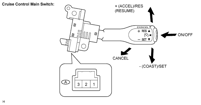
Measure the resistance according to the value(s) in the table below.
| Tester Connection | Switch Condition | Specified Condition |
| A-1 (CCS) - A-3 (ECC) | Neutral | 10 kΩ or higher |
| + (ACCEL)/RES (RESUME) | 216 to 264 Ω | |
| - (COAST)/SET | 567 to 693 Ω | |
| CANCEL | 1,386 to 1,694 Ω | |
| Main Switch on | Below 1 Ω |
|
| ||||
| OK | |
|
| 3.CHECK HARNESS AND CONNECTOR (CRUISE CONTROL MAIN SWITCH - SPIRAL CABLE) |
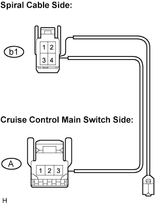 |
Disconnect the b1 connector from the spiral cable.
Measure the resistance according to the value(s) in the table below.
| Tester connection | Condition | Specified condition |
| A-1 - b1-3 | Always | Below 1 Ω |
| A-3 - b1-4 | Always | Below 1 Ω |
|
| ||||
| OK | |
|
| 4.CHECK SPIRAL CABLE |
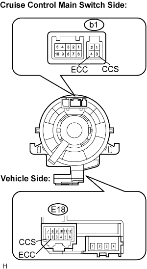 |
Remove the spiral cable.
Measure the resistance according to the value(s) in the table below.
| Tester Connection | Spiral Cable Position | Specified Condition |
| b1-3 - E18-1 (CCS) | Center | Below 1 Ω |
| 2.5 rotations to the left | ||
| 2.5 rotations to the right | ||
| b1-4 - E18-2 (ECC) | Center | Below 1 Ω |
| 2.5 rotations to the left | ||
| 2.5 rotations to the right |
|
| ||||
| OK | |
|
| 5.CHECK WIRE HARNESS (SPIRAL CABLE - ECM AND BODY GROUND) |
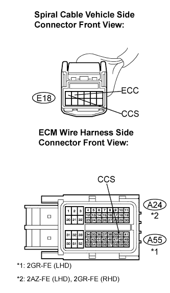 |
Measure the resistance according to the value(s) in the table below.
| Tester Connection | Condition | Specified Condition |
| E18-1 - A55-40 (CCS)*1
E18-1 - A24-40 (CCS)*2 | Always | Below 1 Ω |
| A55-40 (CCS) - Body ground*1
A24-40 (CCS) - Body ground*2 | Always | 10 kΩ or higher |
| E18-2 (ECC) - Body ground | Always | Below 1 Ω |
|
| ||||
| OK | ||
 | ||
| ||
