ENGINE IMMOBILISER SYSTEM (w/ Entry and Start System) > TERMINALS OF ECU |
| CHECK ENGINE SWITCH |
Disconnect the E70 engine switch connector.

Measure the resistance according to the value(s) in the table below.
| Tester Connection | Wiring Color | Terminal Description | Condition | Specified Condition |
| E70-8 (AGND) - Body ground | G - Body ground | Ground | Always | Below 1 Ω |
Reconnect the E70 engine switch connector.
Measure the voltage according to the value(s) in the table below.
| Tester Connection | Wiring Color | Terminal Description | Condition | Specified Condition |
| E70-9 (TXCT) - E70-8 (AGND) | GR - G | Key code output signal | Key not in cabin | Below 1 V |
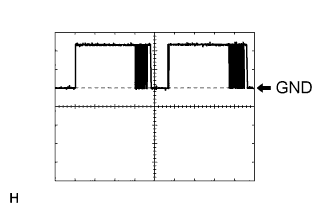
| E70-9 (TXCT) - E70-8 (AGND) | GR - G | Key code output signal | Key held close to engine switch* | Pulse generation (See waveform 1) |
| E70-10 (CODE) - E70-8 (AGND) | W - G | Demodulated signal of key code data | Key not in cabin | Below 1 V |
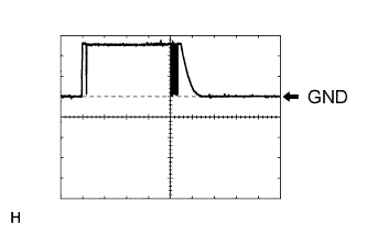
| E70-10 (CODE) - E70-8 (AGND) | W - G | Demodulated signal of key code data | Key held close to engine switch* | Pulse generation (See waveform 2) |
| E70-14 (VC5) - E70-8 (AGND) | R - G | Power supply | Key not in cabin | Below 1 V |
| E70-14 (VC5) - E70-8 (AGND) | R - G | Power supply | Brake pedal depressed* | 4.6 to 5.4 V |
Inspect using an oscilloscope.
![]() |
Waveform 1 (Reference)
| Item | Content |
| Tester Connection | E70-9 (TXCT) - E70-8 (AGND) |
| Tool Setting | 2 V/DIV., 50 ms./DIV. |
| Condition | Key is held close to engine switch* |
![]() |
Waveform 2 (Reference)
| Item | Content |
| Tester Connection | E70-10 (CODE) - E70-8 (AGND) |
| Tool Setting | 2 V/DIV., 50 ms./DIV. |
| Condition | Key is held close to engine switch* |
| CHECK CERTIFICATION ECU (SMART KEY ECU ASSEMBLY) |
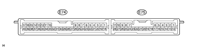
Disconnect the E74 certification ECU (smart key ECU assembly) connector.

Measure the resistance and voltage according to the value(s) in the table below.
| Tester Connection | Wiring Color | Terminal Description | Condition | Specified Condition |
| E74-1 (+B) - E74-17 (E) | W - W-B | +B power supply | Always | 11 to 14 V |
| E74-17 (E) - Body ground | W-B - Body ground | Ground | Always | Below 1 Ω |
Reconnect the E74 certification ECU (smart key ECU assembly) connector.
Measure the resistance and voltage according to the value(s) in the table below.
| Tester Connection | Wiring Color | Terminal Description | Condition | Specified Condition |
| E74-2 (IND) - Body ground | Y - Body ground | Security indicator light signal | Engine switch on (IG), security indicator light off | Below 1 V |
| E74-2 (IND) - Body ground | Y - Body ground | Security indicator light signal | Immobiliser set state, security indicator light blinks | Repeats 11 to 14 V and below 1 V |
| E74-8 (TXCT) - E74-40 (AGND) | GR - G | Engine switch TXCT output | Key not in cabin | Below 1 V |
| E74-8 (TXCT) - E74-40 (AGND) | GR - G | Engine switch TXCT output | Key held close to engine switch* | Pulse generation (See waveform 1) |
| E74-9 (CODE) - E74-40 (AGND) | W - G | Engine switch CODE input | Key not in cabin | Below 1 V |
| E74-9 (CODE) - E74-40 (AGND) | W - G | Engine switch CODE input | Key held close to engine switch* | Pulse generation (See waveform 2) |
| E74-18 (IG) - E74-17 (E) | LG - W-B | Ignition power supply | Engine switch off | Below 1 V |
| E74-18 (IG) - E74-17 (E) | LG - W-B | Ignition power supply | Engine switch on (IG) | 11 to 14 V |
| E74-19 (ACC) - E74-17 (E) | L - W-B | ACC power supply | Engine switch off | Below 1 V |
| E74-19 (ACC) - E74-17 (E) | L - W-B | ACC power supply | Engine switch on (ACC) | 11 to 14 V |
| E74-30 (VC5) - E74-40 (AGND) | R - G | Engine switch power supply | Key not in cabin | Below 1 V |
| E74-30 (VC5) - E74-40 (AGND) | R - G | Engine switch power supply | Brake pedal depressed* | 4.6 to 5.4 V |
| E74-40 (AGND) - Body ground | G - Body ground | Engine switch ground | Always | Below 1 Ω |
Inspect using an oscilloscope.
![]() |
Waveform 1 (Reference)
| Item | Content |
| Tester Connection | E74-8 (TXCT) - E74-40 (AGND) |
| Tool Setting | 2 V/DIV., 50 ms./DIV. |
| Condition | Key is held close to engine switch* |
![]() |
Waveform 2 (Reference)
| Item | Content |
| Tester Connection | E74-9 (CODE) - E74-40 (AGND) |
| Tool Setting | 2 V/DIV., 50 ms./DIV. |
| Condition | Key is held close to engine switch* |
| CHECK ID CODE BOX (IMMOBILISER CODE ECU) |
Disconnect the E68 ID code box (immobiliser code ECU) connector.

Measure the resistance and voltage according to the value(s) in the table below.
| Tester Connection | Wiring Color | Terminal Description | Condition | Specified Condition |
| E68-1 (+B) - E68-8 (GND) | W - W-B | +B power supply | Always | 11 to 14 V |
| E68-8 (GND) - Body ground | W-B - Body ground | Ground | Always | Below 1 Ω |
Reconnect the E68 ID code box (immobiliser code ECU) connector.
Measure the voltage according to the value(s) in the table below.
| Tester Connection | Wiring Color | Terminal Description | Condition | Specified Condition |
| E68-5 (EFII) - E68-8 (GND) | G - W-B | ECM input signal | Engine switch off | Below 1 V |
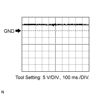
| E68-5 (EFII) - E68-8 (GND) | G - W-B | ECM input signal | Engine switch on (IG) | Pulse generation (See waveform 1) |
| E68-6 (EFIO) - E68-8 (GND) | L - W-B | ECM output signal | Engine switch off | Below 1 V |
| E68-6 (EFIO) - E68-8 (GND) | L - W-B | ECM output signal | Engine switch on (IG) | Pulse generation (See waveform 2) |
Inspect using an oscilloscope.
![]() |
Waveform 1 (Reference)
| Item | Content |
| Tester Connection | E68-5 (EFII) - E68-8 (GND) |
| Tool Setting | 5 V/DIV., 100 ms./DIV. |
| Condition | Engine switch on (IG) |
![]() |
Waveform 2 (Reference)
| Item | Content |
| Tester Connection | E68-6 (EFIO) - E68-8 (GND) |
| Tool Setting | 5 V/DIV., 100 ms./DIV. |
| Condition | Engine switch on (IG) |
| CHECK STEERING LOCK ECU (STEERING LOCK ACTUATOR ASSEMBLY) |
Disconnect the E69 steering lock ECU (steering lock actuator assembly) connector.

Measure the resistance and voltage according to the value(s) in the table below.
| Tester Connection | Wiring Color | Terminal Description | Condition | Specified Condition |
| E69-1 (GND) - Body ground | W-B - Body ground | Ground | Always | Below 1 Ω |
| E69-2 (SGND) - Body ground | W-B - Body ground | Ground | Always | Below 1 Ω |
| E69-6 (IG2) - Body ground | B - Body ground | Ignition power supply | Engine switch off | Below 1 V |
| E69-6 (IG2) - Body ground | P - Body ground | Ignition power supply | Engine switch on (IG) | 11 to 14 V |
| E69-7 (B) - Body ground | P - Body ground | +B power supply | Always | 11 to 14 V |
| CHECK ECM |
The values listed under "Specified Condition" are reference values. Because waterproof connectors are used for the ECM, inspections can not be performed with the connectors connected.

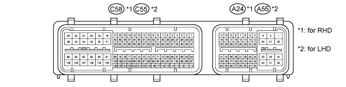
| Tester Connection | Wiring Color | Terminal Description | Condition | Specified Condition |
| C58-81 (E1) - Body ground | W-B - Body ground | Ground | Always | Below 1 Ω |
| A24-10 (IMO) - C58-81 (E1) | G - W-B | ID code box (immobiliser code ECU) output signal | Engine switch off | Below 1 V |
| A24-10 (IMO) - C58-81 (E1) | G - W-B | ID code box (immobiliser code ECU) output signal | Engine switch on (IG) | Pulse generation (See waveform 1) |
| A24-11 (IMI) - C58-81 (E1) | Y - W-B | ID code box (immobiliser code ECU) input signal | Engine switch off | Below 1 V |
| A24-11 (IMI) - C58-81 (E1) | Y - W-B | ID code box (immobiliser code ECU) input signal | Engine switch on (IG) | Pulse generation (See waveform 2) |
| Tester Connection | Wiring Color | Terminal Description | Condition | Specified Condition |
| C55-81 (E1) - Body ground | W-B - Body ground | Ground | Always | Below 1 Ω |
| A55-10 (IMO) - C55-81 (E1) | G - W-B | ID code box (immobiliser code ECU) output signal | Engine switch off | Below 1 V |
| A55-10 (IMO) - C55-81 (E1) | G - W-B | ID code box (immobiliser code ECU) output signal | Engine switch on (IG) | Pulse generation (See waveform 1) |
| A55-11 (IMI) - C55-81 (E1) | Y - W-B | ID code box (immobiliser code ECU) input signal | Engine switch off | Below 1 V |
| A55-11 (IMI) - C55-81 (E1) | Y - W-B | ID code box (immobiliser code ECU) input signal | Engine switch on (IG) | Pulse generation (See waveform 2) |
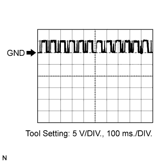
Waveform:
![]() |
Waveform 1 (Reference)
| Item | Content | |
| Tester Connection | for RHD | A24-10 (IMO) - C58-81 (E1) |
| for LHD | A55-10 (IMO) - C55-81 (E1) | |
| Tool Setting | 5 V/DIV., 100 ms./DIV. | |
| Condition | Engine switch on (IG) | |
![]() |
Waveform 2 (Reference)
| Item | Content | |
| Tester Connection | for RHD | A24-11 (IMI) - C58-81 (E1) |
| for LHD | A55-11 (IMI) - C55-81 (E1) | |
| Tool Setting | 5 V/DIV., 100 ms./DIV. | |
| Condition | Engine switch on (IG) | |
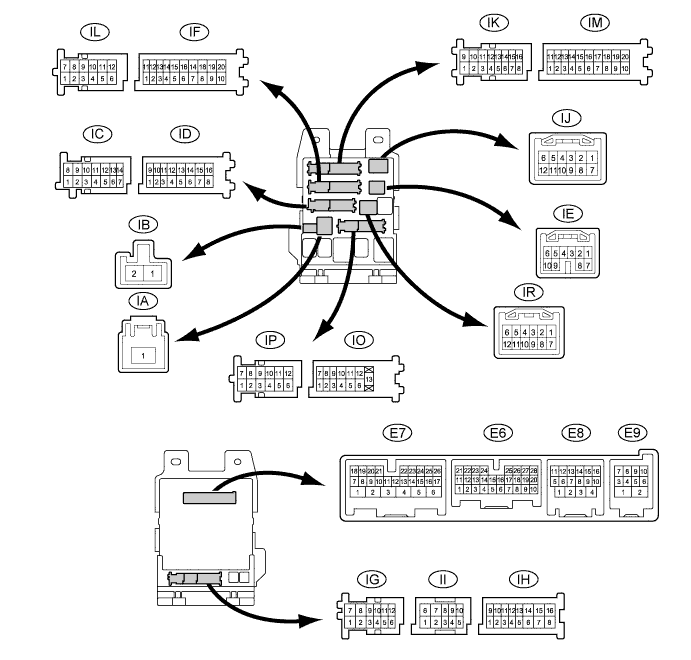
| CHECK MAIN BODY ECU (INSTRUMENT PANEL JUNCTION BLOCK ASSEMBLY) |
Disconnect the ID, IM and IR main body ECU (instrument panel junction block assembly) connectors.

Measure the voltage and resistance according to the value(s) in the table below.
| Tester Connection | Wiring Color | Terminal Description | Condition | Specified Condition |
| ID-10 (BECU) - Body ground | BE - Body ground | Battery power supply | Always | 11 to 14 V |
| ID-16 (ALTB) - Body ground | W - Body ground | Battery power supply | Always | 11 to 14 V |
| IM-9 (GND1) - Body ground | W-B - Body ground | Ground | Always | Below 1 Ω |
| IR-1 (GND2) - Body ground | W-B - Body ground | Ground | Always | Below 1 Ω |
| CLOCK ASSEMBLY |
Disconnect the F3 clock assembly connector.

Measure the voltage and resistance according to the value(s) in the table below.
| Terminal No. (Symbol) | Wiring Color | Terminal Description | Condition | Specified Condition |
| F3-1 (B) - Body ground | R - Body ground | Battery | Always | 11 to 14 V |
| F3-3 (IG) - Body ground | GR - Body ground | Engine switch signal | Engine switch on (IG) | 11 to 14 V |
| F3-3 (IG) - Body ground | GR - Body ground | Engine switch signal | Engine switch off | Below 1 V |
| F3-8 (LP) - Body ground | Y - Body ground | Security indicator light signal | Engine switch on (IG), security indicator light off | Below 1 V |
| F3-8 (LP) - Body ground | Y - Body ground | Security indicator light signal | Immobiliser set state, security indicator light blinks | Repeats 11 to 14 V and below 1 V |
| F3-19 (GND1) - Body ground | W-B - Body ground | Ground (Signal ground) | Always | Below 1 Ω |