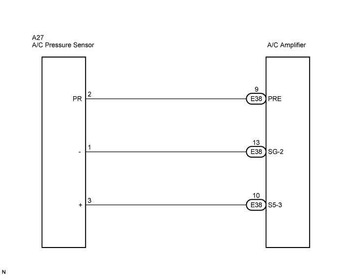
DTC B1423/23 Pressure Sensor Circuit |
| DTC No. | DTC Detection Condition | Trouble Area |
| B1423/23 | Open or short in pressure sensor circuit |
|
| 1.CHECK REFRIGERANT PRESSURE |
Install the manifold gauge set .
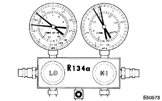 |
Read the manifold gauge pressure when the following conditions are established.
Prepare the vehicle according to the chart below.
| Item | Condition |
| Vehicle Doors | Fully open |
| Temperature Setting | MAX COLD |
| Blower Speed | HI |
| A/C Switch | ON |
| R/F Switch | RECIRCULATION (30 to 35°C (86 to 95°F)) |
|
| ||||
| OK | |
 |
| 2.CHECK HARNESS AND CONNECTOR (PRESSURE SENSOR - A/C AMPLIFIER) |
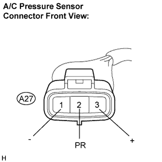 |
Disconnect the pressure sensor connector.
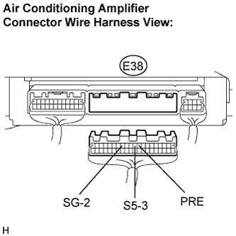 |
Disconnect the A/C amplifier connector.
Measure the resistance according to the value(s) in the table below.
| Tester Connection | Condition | Specified Condition |
| A27-2 (PR) - E38-9 (PRE) | Always | Below 1 Ω |
| A27-3 (+) - E38-10 (S5-3) | Always | Below 1 Ω |
| A27-1 (-) - E38-13 (SG-2) | Always | Below 1 Ω |
| E38-9 (PRE) - Body ground | Always | 10 kΩ or higher |
| E38-10 (S5-3) - Body ground | Always | 10 kΩ or higher |
| E38-13 (SG-2) - Body ground | Always | 10 kΩ or higher |
|
| ||||
| OK | |
|
| 3.INSPECT PRESSURE SENSOR |
Install the manifold gauge set .
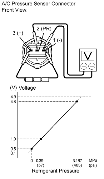 |
Connect the three 1.5 V dry cell batterie's positive (+) lead to terminal 3, and the negative (-) lead to terminal 1. Then connect the voltmeter's positive (+) lead to terminal 2, and the negative (-) lead to terminal 1. Measure the voltage.
| Result | Proceed to |
| NG | A |
| OK (When troubleshooting according to the DTC) | B |
| OK (When troubleshooting according to the PROBLEM SYMPTOMS TABLE) | C |
|
| ||||
|
| ||||
| A | ||
 | ||
| ||
