Home › RESTRAINTS › SUPPLEMENTAL RESTRAINT SYSTEM › CENTER AIRBAG SENSOR ASSEMBLY

CENTER AIRBAG SENSOR ASSEMBLY > INSTALLATION

for Preparation Click here


1. INSTALL CENTER AIRBAG SENSOR ASSEMBLY
  1. Check that the ignition switch is off.

  1. Check that the battery negative (-) cable is disconnected.

    CAUTION:
    Wait for 90 seconds after disconnecting the cable to prevent airbag deployment.


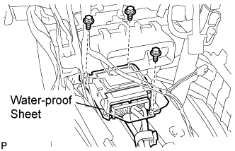
    C133884E01
  1. Install the center airbag sensor assembly with the 3 bolts.

    Torque:
    17.5 N*m{ 179 kgf*cm , 13 ft.*lbf }

    NOTICE:
    1. If the center airbag sensor assembly has been dropped, or there are any cracks, dents or other defects in the case, bracket or connector, replace it with a new one.
    2. When installing the center airbag sensor assembly, be careful that the SRS wiring does not interfere with other parts and that it is not pinched between other parts.
  1. Check that there is no looseness in the installation parts of the center airbag sensor assembly.

  1. Connect the holder (with connectors).

  1. Check that the water-proof sheet is properly set.


2. INSTALL NO. 1 CONSOLE BOX DUCT (w/ Rear Register Duct)


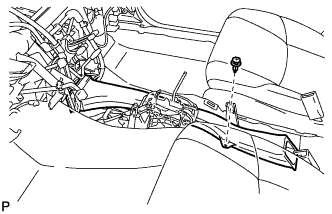
    C129716
  1. Install the No. 1 console box duct with the clip.


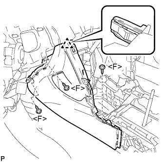
3. INSTALL NO. 2 CONSOLE BOX INSERT FRONT


    B134005E01
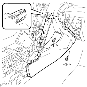
  1. Engage the clip.

  1. Install the No. 2 console box insert front with the 3 screws <F>.


4. INSTALL NO. 1 CONSOLE BOX INSERT FRONT


    B134006E01
  1. Engage the clip.

  1. Install the No. 1 console box insert front with the 3 screws <F>.


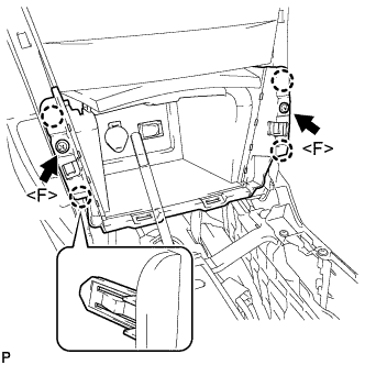
5. INSTALL CONSOLE BOX ASSEMBLY


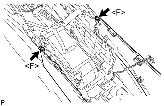
    B134002E01
  1. Install the 2 screws <F>.


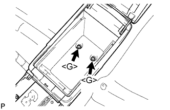
    B134003E01
  1. Install the console box assembly with the 2 bolts <G>.


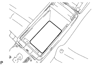
6. INSTALL CONSOLE BOX CARPET


    B134004
  1. Install the console box carpet.


7. INSTALL CONSOLE BOX POCKET
  1. Install the console box pocket.


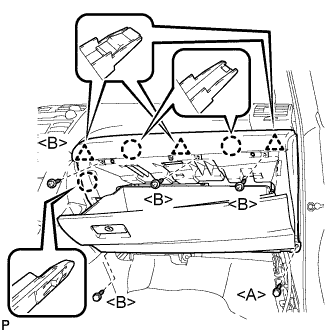
8. INSTALL LOWER INSTRUMENT PANEL SUB-ASSEMBLY


    B133992E01
  1. Engage the 3 claws and 3 clips.

  1. Install the 4 screws <B>.

  1. Install the lower instrument panel sub-assembly with the bolt <A>.


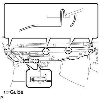
9. INSTALL INSTRUMENT PANEL NO. 2 UNDER COVER SUB-ASSEMBLY


    B133989E01
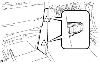
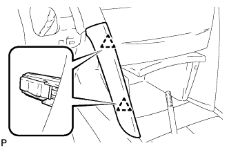
  1. Engage the 4 claws and 2 guides and install the instrument panel No. 2 under cover.


10. INSTALL COWL SIDE TRIM SUB-ASSEMBLY RH

HINT:
Use the same procedures for the RH side and the LH side.


11. INSTALL FRONT DOOR SCUFF PLATE RH

HINT:
Use the same procedures for the RH side and the LH side.


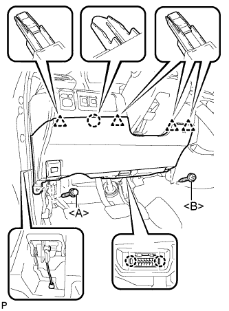
12. INSTALL LOWER INSTRUMENT PANEL FINISH PANEL LH


    B147263E01
  1. Install the air hose and connect the connector.

  1. Engage the 2 claws and the DLC3.

  1. Engage the claw and the 4 clips.

  1. Instal the lower instrument panel finish panel LH with the screw <B> and bolt <A>.


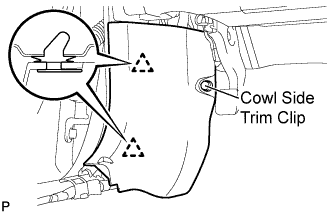
13. INSTALL COWL SIDE TRIM SUB-ASSEMBLY LH


    B132116E01
  1. Engage the 2 clips.

  1. Install the cowl side trim sub-assembly LH with the cowl side trim clip.


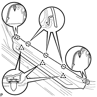
14. INSTALL FRONT DOOR SCUFF PLATE LH


    B132067
  1. Engage the 7 claws and 3 clips, then install the front door scuff plate LH.


15. INSTALL UPPER CONSOLE PANEL SUB-ASSEMBLY
  1. Connect each connector.


    B133997E01
  1. Engage the 4 claws.

  1. Install the upper console panel sub-assembly with the 2 screws <F>.


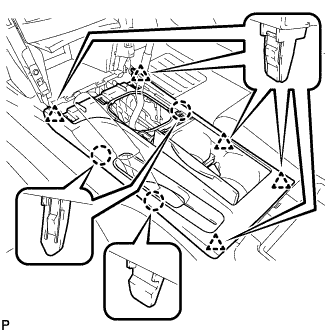
16. INSTALL UPPER CONSOLE REAR PANEL SUB-ASSEMBLY (for Manual Transaxle)


    B137277
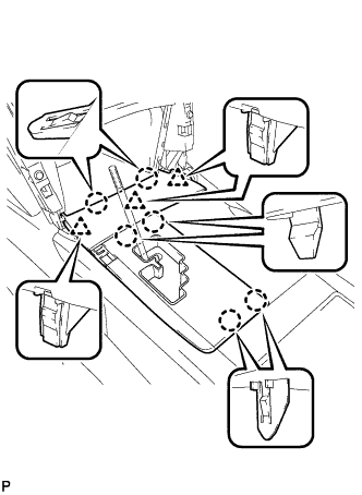
  1. Engage the 3 claws and 5 clips to install the upper console rear panel sub-assembly.


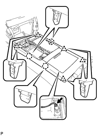
17. INSTALL UPPER CONSOLE REAR PANEL SUB-ASSEMBLY (for Automatic Transaxle)


    B226097
  1. Connect the connector.

  1. Engage the 3 claws and 5 clips to install the upper console rear panel sub-assembly.


18. INSTALL UPPER CONSOLE PANEL (for Manual Transaxle)


    B137276
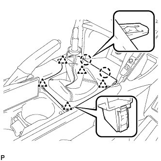
  1. Engage the 2 claws and the 5 clips to install the upper console panel as shown in the illustration.


19. INSTALL FLOOR SHIFT POSITION INDICATOR HOUSING SUB-ASSEMBLY (for Automatic Transaxle)
  1. with Seat Heater System:

    1. Connect each connector.


    B226065
  1. Engage the 6 claws and the 3 clips to install the floor shift position indicator housing sub-assembly.


20. INSTALL NO. 2 INSTRUMENT CLUSTER FINISH PANEL GARNISH


    B226064
  1. Engage the 2 clips and install the No. 2 instrument cluster finish panel garnish.


21. INSTALL NO. 1 INSTRUMENT CLUSTER FINISH PANEL GARNISH


    B226063
  1. Engage the 2 clips and install the No. 1 instrument cluster finish panel garnish.


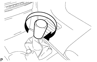
22. INSTALL SHIFT LEVER KNOB SUB-ASSEMBLY (for Manual Transaxle)


    B137273
  1. Install the shift lever knob sub-assembly.


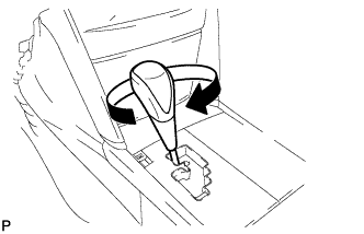
23. INSTALL SHIFT LEVER KNOB SUB-ASSEMBLY (for Automatic Transaxle)


    B227961
  1. Install the shift lever knob sub-assembly.


24. CONNECT CABLE TO NEGATIVE BATTERY TERMINAL


25. INSPECT SRS WARNING LIGHT
  1. Inspect the SRS warning light (Click here).