 |
Connect the 2 connectors.
FRONT PASSENGER AIRBAG ASSEMBLY > INSTALLATION |
| 1. INSTALL INSTRUMENT PANEL WIRE ASSEMBLY |
|
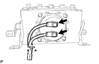
Connect the 2 connectors.
Install the clamp and the instrument panel wire assembly on the front passenger airbag assembly.
| 2. INSTALL FRONT PASSENGER AIRBAG ASSEMBLY |
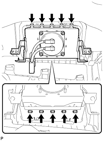 |
Engage the 10 hooks and install the front passenger airbag assembly on the instrument panel safety pad assembly.
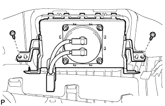 |
Install the 2 screws.
| 3. INSTALL INSTRUMENT PANEL SAFETY PAD ASSEMBLY |
Engage the 5 claws.
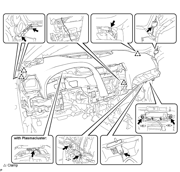
Install the 2 bolts <H> or <O> and 2 nuts <C> or <I>.
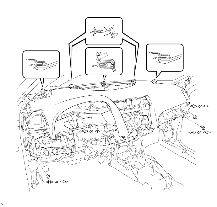
Engage each clamp.
Install the bolt <J>.
Install the 2 passenger airbag bolts <K>.
Connect each connector and install the instrument panel safety pad assembly.
with Plasmacluster:
Connect the connector.
| 4. CONNECT INSTRUMENT PANEL WIRE ASSEMBLY |
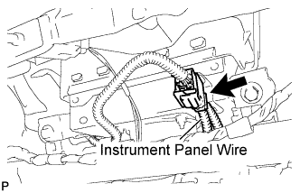 |
Connect the connector (yellow colored one).
| 5. INSTALL NO. 1 DEFROSTER NOZZLE GARNISH |
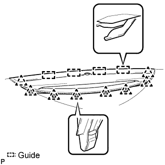 |
Connect each connector.
Engage the 4 guides.
Engage the 8 clips and install the No. 1 defroster nozzle garnish.
| 6. INSTALL FRONT NO. 2 SPEAKER ASSEMBLY (for LH Side) |
Connect the connector.
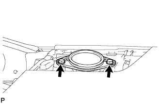 |
Install the front No. 2 speaker assembly with the 2 bolts.
| 7. INSTALL INSTRUMENT PANEL NO. 1 SPEAKER PANEL SUB-ASSEMBLY |
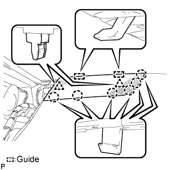 |
Engage the 2 guides.
Engage the 6 claws and the 2 clips to install the instrument panel No. 1 speaker panel sub-assembly.
| 8. INSTALL INSTRUMENT PANEL NO. 1 REGISTER ASSEMBLY |
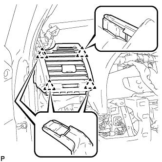 |
Engage the 4 clips and install the instrument panel No. 1 register assembly.
| 9. INSTALL FRONT PILLAR GARNISH LH |
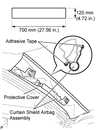 |
Remove the protective cover.
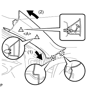 |
Install a new clip <A> on the front pillar garnish LH.
Engage the 2 claws and 2 clips, then install the front pillar garnish LH.
| 10. INSTALL FRONT NO. 2 SPEAKER ASSEMBLY (for RH Side) |
| 11. INSTALL INSTRUMENT PANEL NO. 2 SPEAKER PANEL SUB-ASSEMBLY |
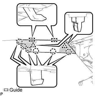 |
Engage the 2 guides.
Engage the 6 claws and the 2 clips to install the instrument panel No. 2 speaker panel sub-assembly.
| 12. INSTALL INSTRUMENT PANEL NO. 3 REGISTER ASSEMBLY |
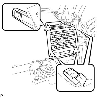 |
Engage the 4 clips and install the instrument panel No. 3 register assembly.
| 13. INSTALL FRONT PILLAR GARNISH RH |
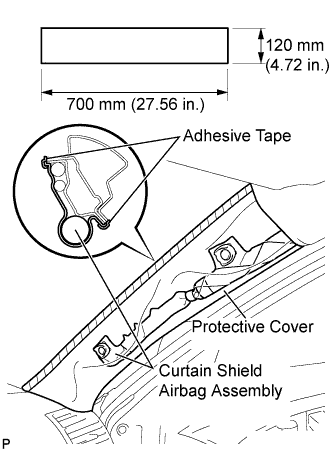 |
Remove the protective cover.
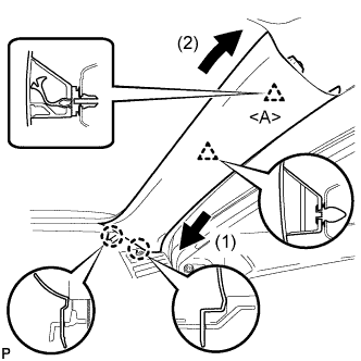 |
Install a new clip <A> on the front pillar garnish RH.
Engage the 2 claws and 2 clips, then install the front pillar garnish RH.
| 14. INSTALL NO. 1 CONSOLE BOX INSERT FRONT |
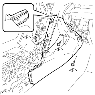 |
Engage the clip.
Install the No. 1 console box insert front with the 3 screws <F>.
| 15. INSTALL NO. 2 CONSOLE BOX INSERT FRONT |
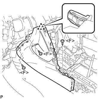 |
Engage the clip.
Install the No. 2 console box insert front with the 3 screws <F>.
| 16. INSTALL CONSOLE BOX ASSEMBLY |
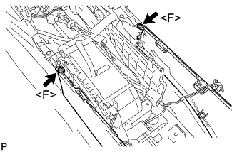 |
Install the 2 screws <F>.
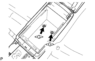 |
Install the console box assembly with the 2 bolts <G>.
| 17. INSTALL CONSOLE BOX CARPET |
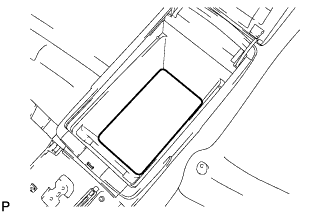 |
Install the console box carpet.
| 18. INSTALL CONSOLE BOX POCKET |
Install the console box pocket.
| 19. INSTALL RADIO TUNER OPENING COVER WITH HEATER CONTROL PANEL ASSEMBLY (w/o Radio Receiver) |
Connect the connector.
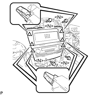 |
Engage the 6 clips.
Install the radio tuner opening cover with heater control panel assembly with the 4 bolts <N>.
| 20. INSTALL RADIO RECEIVER WITH HEATER CONTROL PANEL ASSEMBLY (w/ Radio Receiver) |
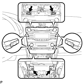 |
Connect each connector.
Engage the 4 clips.
Install the radio receiver with heater control panel assembly with the 4 bolts.
| 21. INSTALL NAVIGATION RECEIVER WITH HEATER CONTROL PANEL ASSEMBLY (w/ Navigation System) |
Connect each connector.
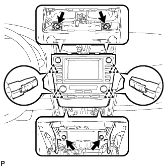 |
Engage the 4 clips.
Install the navigation receiver with heater control panel assembly with the 4 bolts.
| 22. INSTALL INSTRUMENT PANEL NO. 2 REGISTER ASSEMBLY |
Connect the connector.
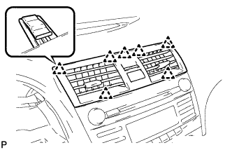 |
Engage the 7 clips and install the instrument panel No. 2 register assembly.
| 23. INSTALL UPPER CONSOLE PANEL SUB-ASSEMBLY |
Connect each connector.
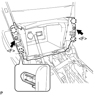 |
Engage the 4 claws.
Install the upper console panel sub-assembly with the 2 screws <F>.
| 24. INSTALL UPPER CONSOLE REAR PANEL SUB-ASSEMBLY (for Automatic Transaxle) |
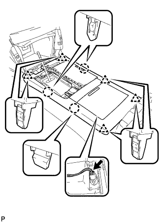 |
Connect the connector.
Engage the 3 claws and 5 clips to install the upper console rear panel sub-assembly.
| 25. INSTALL UPPER CONSOLE REAR PANEL SUB-ASSEMBLY (for Manual Transaxle) |
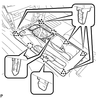 |
Engage the 3 claws and 5 clips to install the upper console rear panel sub-assembly.
| 26. INSTALL FLOOR SHIFT POSITION INDICATOR HOUSING SUB-ASSEMBLY (for Automatic Transaxle) |
with Seat Heater System:
Connect each connector.
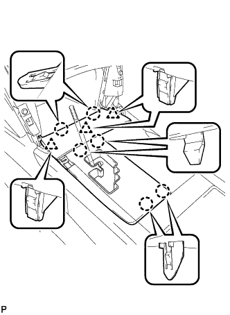 |
Engage the 6 claws and the 3 clips to install the floor shift position indicator housing sub-assembly.
| 27. INSTALL UPPER CONSOLE PANEL (for Manual Transaxle) |
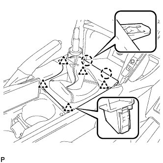 |
Engage the 2 claws and the 5 clips to install the upper console panel as shown in the illustration.
| 28. INSTALL NO. 2 INSTRUMENT CLUSTER FINISH PANEL GARNISH |
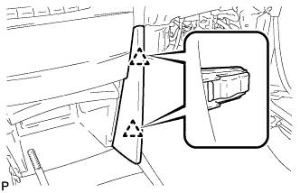 |
Engage the 2 clips and install the No. 2 instrument cluster finish panel garnish.
| 29. INSTALL NO. 1 INSTRUMENT CLUSTER FINISH PANEL GARNISH |
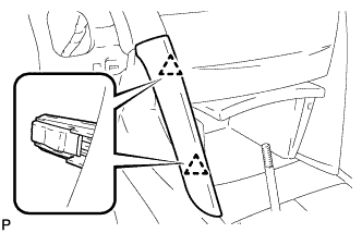 |
Engage the 2 clips and install the No. 1 instrument cluster finish panel garnish.
| 30. INSTALL SHIFT LEVER KNOB SUB-ASSEMBLY (for Automatic Transaxle) |
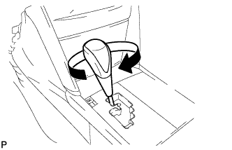 |
Install the shift lever knob sub-assembly.
| 31. INSTALL SHIFT LEVER KNOB SUB-ASSEMBLY (for Manual Transaxle) |
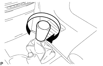 |
Install the shift lever knob sub-assembly.
| 32. INSTALL LOWER INSTRUMENT PANEL SUB-ASSEMBLY |
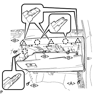 |
Engage the 3 claws and 3 clips.
Install the 4 screws <B>.
Install the lower instrument panel sub-assembly with the bolt <A>.
| 33. INSTALL INSTRUMENT PANEL NO. 2 UNDER COVER SUB-ASSEMBLY |
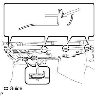 |
Engage the 4 claws and 2 guides and install the instrument panel No. 2 under cover.
| 34. INSTALL COWL SIDE TRIM SUB-ASSEMBLY RH |
| 35. INSTALL FRONT DOOR SCUFF PLATE RH |
| 36. INSTALL COMBINATION METER ASSEMBLY |
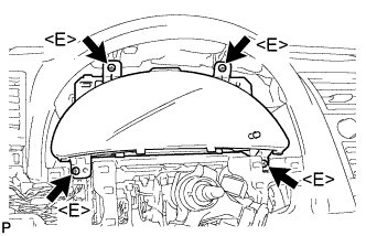 |
Connect each connector.
Install the combination meter assembly with the 4 screws <E>.
| 37. INSTALL INSTRUMENT CLUSTER FINISH PANEL NO.1 |
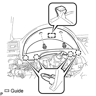 |
Engage the guide and the 4 claws.
Install the instrument cluster finish panel with the 2 clips.
| 38. INSTALL LOWER INSTRUMENT PANEL FINISH PANEL (w/o Entry and Start System) |
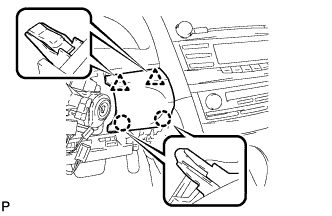 |
Engage the 2 claws and 2 clips to install the lower instrument panel finish panel.
| 39. INSTALL LOWER INSTRUMENT PANEL FINISH PANEL (w/ Entry and Start System) |
Connect the connector.
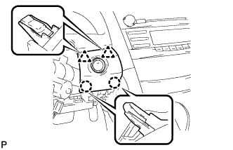 |
Engage the 2 claws and 2 clips to install the lower instrument panel finish panel.
| 40. INSTALL NO. 1 INSTRUMENT PANEL SUB-ASSEMBLY |
Connect each connector.
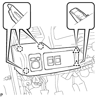 |
Engage the 3 claws and 2 clips to install the No. 1 instrument panel sub-assembly.
| 41. INSTALL TURN SIGNAL SWITCH ASSEMBLY WITH SPIRAL CABLE |
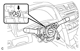 |
Install the turn signal switch assembly with spiral cable sub-assembly to the steering column assembly with the clamp.
Connect the connectors to the turn signal switch assembly with spiral cable sub-assembly.
| 42. INSTALL STEERING COLUMN COVER |
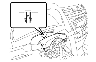 |
Engage the claw to install the upper steering column cover.
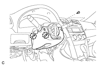 |
Engage the 2 claws to install the lower steering column cover.
Install the 2 screws.
| 43. ADJUST SPIRAL CABLE |
Check that the ignition switch is off.
Check that the battery negative (-) cable is disconnected.
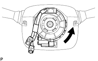 |
Rotate the spiral cable counterclockwise slowly by hand until it feels firm.
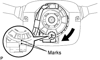 |
Rotate the spiral cable clockwise approximately 2.5 turns to align the marks.
| 44. INSTALL LOWER INSTRUMENT PANEL FINISH PANEL LH |
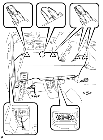 |
Install the air hose and connect the connector.
Engage the 2 claws and the DLC3.
Engage the claw and the 4 clips.
Instal the lower instrument panel finish panel LH with the screw <B> and bolt <A>.
| 45. INSTALL COWL SIDE TRIM SUB-ASSEMBLY LH |
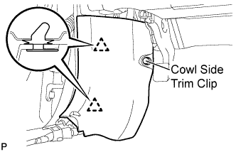 |
Engage the 2 clips.
Install the cowl side trim sub-assembly LH with the cowl side trim clip.
| 46. INSTALL FRONT DOOR SCUFF PLATE LH |
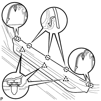 |
Engage the 7 claws and 3 clips, then install the front door scuff plate LH.
| 47. INSTALL STEERING WHEEL ASSEMBLY |
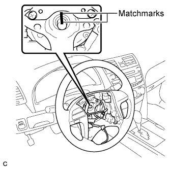 |
Align the matchmarks on the steering wheel assembly and steering main shaft.
Install the steering wheel assembly set nut.
Connect the connectors to the spiral cable sub-assembly.
| 48. INSTALL STEERING PAD |
Check that the ignition switch is off.
Check that the battery negative (-) terminal is disconnected.
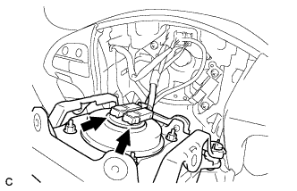 |
Support the steering pad with one hand.
Connect the 2 airbag connectors to the steering pad.
Connect the horn connector to the steering pad.
Confirm that the circumference groove of the "TORX" screw fits in the screw case, and place the steering pad onto the steering wheel assembly.
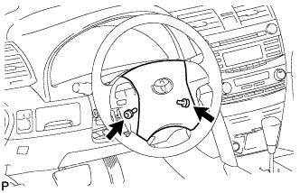 |
Using a "TORX" socket (T30), tighten the 2 "TORX" screws.
| 49. INSTALL NO. 3 LOWER STEERING WHEEL COVER |
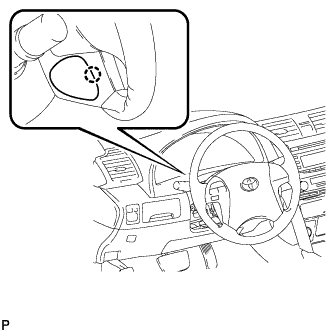 |
Engage the claw and install the No. 3 lower steering wheel cover.
| 50. INSTALL NO. 2 LOWER STEERING WHEEL COVER |
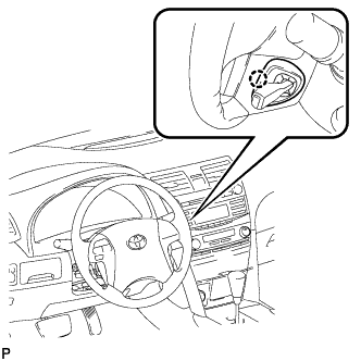 |
Engage the claw and install the No. 2 lower steering wheel cover.
| 51. CONNECT CABLE TO NEGATIVE BATTERY TERMINAL |
| 52. INSPECT STEERING PAD |
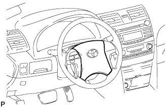 |
With the steering pad installed on the vehicle, perform a visual check. If there are any defects as mentioned below, replace the steering pad with a new one:
Make sure that the horn sounds.
| 53. INSPECT SRS WARNING LIGHT |
Inspect the SRS warning light (Click here).