TOYOTA PARKING ASSIST-SENSOR SYSTEM > OPERATION CHECK |
| SELF-CHECK FUNCTION INSPECTION |
|
Turn the ignition switch to ON.
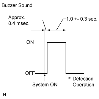
When the clearance sonar system is turned on, check that the following occurs: 1) after 0.4 milliseconds, the buzzer sounds for approximately 1 +- 0.3 seconds, and 2) the system starts the obstacle detection operation.
| MALFUNCTION DISPLAY (MULTI-INFORMATION DISPLAY) |
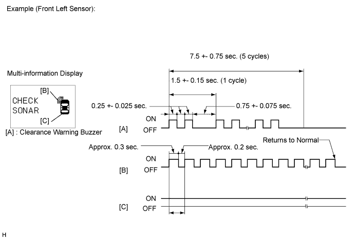
Ultrasonic sensor open circuit
If there is an open circuit between the ultrasonic sensor and the clearance warning ECU or if a sensor is malfunctioning, the malfunction is displayed as shown in the illustration.
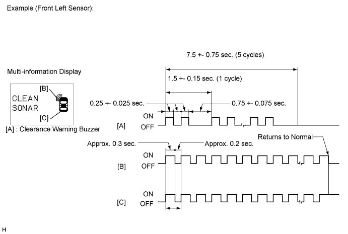
Ultrasonic sensor frozen
If a sensor is covered with foreign matter, such as mud or snow, the affected sensor is displayed as shown in the illustration.
| DETECTION RANGE MEASUREMENT AND DISPLAY INSPECTION |
Detection range measurement
Turn the ignition switch to ON.
Move the shift lever to the reverse position to check the ultrasonic sensors (rear sensors).
Turn the clearance sonar main switch on.
Move a φ 60 mm (2.36 in.) pole near each sensor to measure its detection range.
Measure the clearance sonar's detection range.
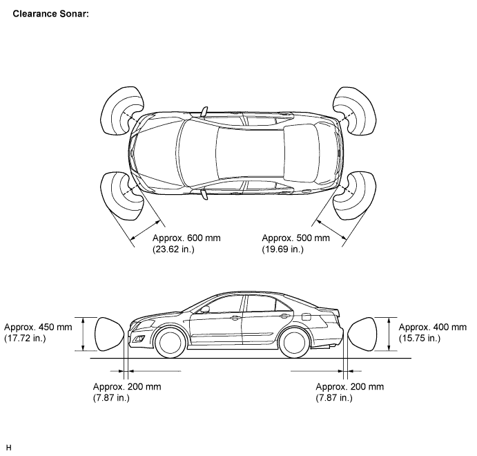
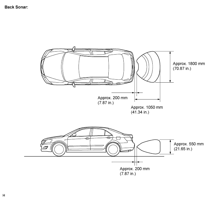
Measure the back sonar's detection range.
When the ultrasonic sensors (front clearance sonar) have detected an obstacle, check the display and buzzer sound.
| Ignition Switch | Clearance Sonar Main Switch | Shift Lever Position | Vehicle Speed |
| ON (IG) | ON | In any position except P |
|
Check the buzzer sound according to the waveform shown in the illustration.
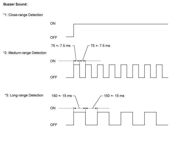
| Detection Range | Condition |
| *1 Close-range detection Within approx. 350 +- 40 mm (13.78 +- 1.57 in.) | Buzzer: Sounds continuously Number of bars displayed: 1 (Blinking) |
| *2 Medium-range detection From approx. 350 +- 40 to 475 +- 50 mm (13.78 +- 1.57 to 18.70 +- 1.97 in.) | Buzzer: Sounds intermittently (ON: 75 ms / OFF: 75 ms) Number of bars displayed: 2 (illuminated) |
| *3 Long-range detection From approx. 475 +- 50 to 600 +- 60 mm (18.70 +- 1.97 to 23.62 +- 2.36 in.) | Buzzer: Sounds intermittently (ON: 150 ms / OFF: 150 ms) Number of bars displayed: 3 (illuminated) |
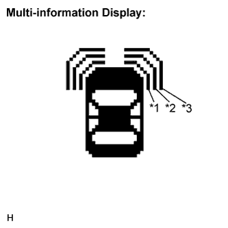 |
Check the display according to the illustration while the buzzer is sounding.
When the ultrasonic sensors (back sonar) have detected an obstacle, check the display and buzzer sound.
| Ignition Switch | Clearance Sonar Main Switch | Shift Lever Position |
| ON (IG) | ON | Reverse Position |
Check the buzzer sound according to the waveform shown in the illustration.
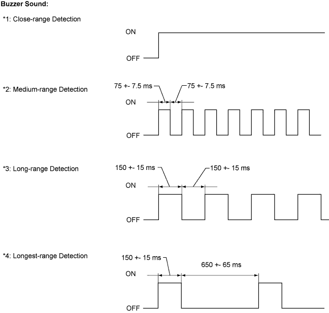
| Detection Range | Condition |
| *1 Close-range detection Within approx. 350 +- 40 mm (13.78 +- 1.57 in.) | Buzzer: Sounds continuously Number of bars displayed: 1 (blinking) |
| *2 Medium-range detection From approx. 350 +- 40 to 450 +- 50 mm (13.78 +- 1.57 to 17.72 +- 1.97 in.) | Buzzer: Sounds intermittently (ON: 75 ms / OFF: 75 ms) Number of bars displayed: 2 (illuminated) |
| *3 Long-range detection From approx. 450 +- 50 to 600 +- 60 mm (17.72 +- 1.97 to 23.62 +- 2.36 in.) | Buzzer: Sounds intermittently (ON: 150 ms / OFF: 150 ms) Number of bars displayed: 3 (illuminated) |
| *4 Longest-range detection From approx. 600 +- 60 to 1,500 +-150 mm (23.62 +- 2.36 to 59.06 +- 5.91 in.) | Buzzer: Sounds intermittently (ON: 150 ms / OFF: 650 ms) Number of bars displayed: 4 (illuminated) |
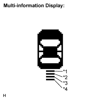 |
Check the display according to the illustration while the buzzer is sounding.
When the ultrasonic sensors (rear clearance sonar) have detected an obstacle, check the display and buzzer sound.
| Ignition Switch | Clearance Sonar Main Switch | Shift Lever Position |
| ON (IG) | ON | Reverse Position |
Check the buzzer sound according to the waveform shown in the illustration.
| Detection Range | Condition |
| *1 Close-range detection Within approx. 250 +- 30 mm (9.84 +- 1.18 in.) | Buzzer: Sounds continuously Number of bars displayed: 1 (Blinking) |
| *2 Medium-range detection From approx. 250 +- 30 to 375 +- 40 mm (9.84 +- 1.18 to 14.76 +- 1.57 in.) | Buzzer: Sounds intermittently (ON: 75 ms / OFF: 75 ms) Number of bars displayed: 2 (illuminated) |
| *3 Long-range detection From approx. 375 +- 40 to 500 +- 50 mm (14.76 +- 1.57 to 19.69 +- 1.97 in.) | Buzzer: Sounds intermittently (ON: 150 ms / OFF: 150 ms) Number of bars displayed: 3 (illuminated) |
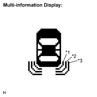 |
Check the display according to the illustration while the buzzer is sounding.