 |
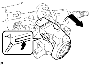
Pull out the transponder key amplifier with the claw open.
- NOTICE:
- Using excessive force may damage the case.
STEERING COLUMN ASSEMBLY > DISASSEMBLY |
| 1. REMOVE TRANSPONDER KEY AMPLIFIER |
Using a screwdriver, widen the claws hanging onto the upper bracket by approximately 1.0 mm (0.039 in.).
|
Pull out the transponder key amplifier with the claw open.
| 2. REMOVE STEERING COLUMN UPPER WITH SWITCH BRACKET ASSEMBLY |
Secure the steering column assembly in a vise.
Using a center punch, mark the center of the 2 tapered-head bolts.
Using a 3 to 4 mm (0.12 to 0.16 in.) diameter drill bit, drill a hole in the 2 tapered-head bolts.
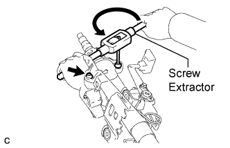 |
Using a screw extractor, remove the 2 tapered-head bolts, and then remove the steering column upper with switch bracket assembly and the steering lock bracket from the steering column assembly.
| 3. REMOVE IGNITION SWITCH LOCK CYLINDER ASSEMBLY |
Turn the ignition switch lock cylinder assembly to the ACC position.
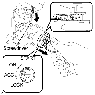 |
Insert a screwdriver into the hole of the steering column upper with switch bracket assembly as shown in the illustration. Pull the ignition switch lock cylinder assembly until its claw contacts the stopper of the steering column upper with switch bracket assembly.
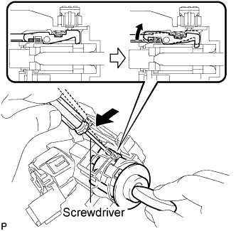 |
Insert a screwdriver into the hole of the steering column upper with switch bracket assembly. Push the screwdriver downward as shown in the illustration to disengage the claw of the ignition switch lock cylinder assembly, and pull out the ignition switch lock cylinder assembly.
| 4. REMOVE UN-LOCK WARNING SWITCH ASSEMBLY |
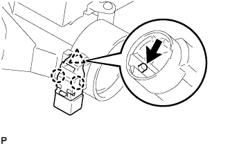 |
Remove the un-lock warning switch assembly by pushing up the center part and releasing the 2 claws.
| 5. REMOVE KEY INTERLOCK SOLENOID (for Automatic Transaxle) |
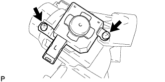 |
Remove the 2 screws and the key interlock solenoid from the steering lock sub-assembly.
| 6. REMOVE IGNITION OR STARTER SWITCH ASSEMBLY |
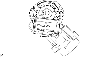 |
Disengage the 2 claws and remove the ignition or starter switch assembly from the steering lock sub-assembly.