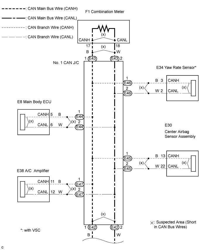
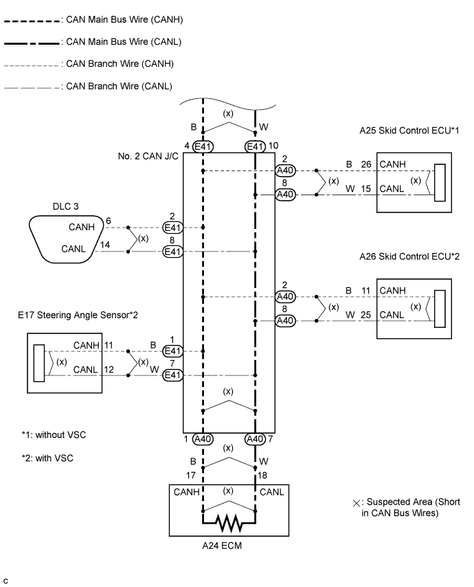
CAN COMMUNICATION SYSTEM (for RHD) > Short in CAN Bus Lines |
| Symptom | Trouble Area |
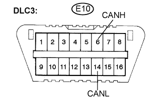
| Resistance between terminals 6 (CANH) and 14 (CANL) of the DLC3 is below 54 Ω. |
|
| 1.CHECK FOR SHORT IN CAN BUS WIRES (DLC3 BRANCH WIRE) |
 |
Turn the ignition switch off.
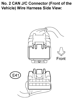
Disconnect the DLC3 branch wire connector (E41) from the No. 2 CAN J/C (front of the vehicle).
 |
Measure the resistance according to the value(s) in the table below.
| Tester Connection | Condition | Specified Value |
| E10-6 (CANH) - E10-14 (CANL) | Ignition switch off | 1 MΩ or higher |
Reconnect the DLC3 branch wire connector (E41) to the No. 2 CAN J/C (front of the vehicle).
|
| ||||
| OK | |
 |
| 2.CHECK FOR SHORT IN CAN BUS WIRES (NO. 1 CAN J/C SIDE) |
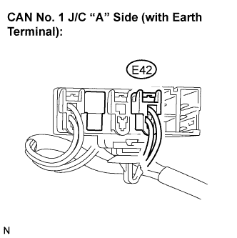 |
Disconnect the CAN main bus wire connector (E42) from the No. 1 CAN J/C "A" side (with earth terminal).
|
Connect the probes of an ohmmeter to terminals 6 (CANH) and 14 (CANL) of the DLC3.
Measure the resistance according to the value(s) in the table below.
| Tester Connection | Condition | Specified Value |
| E10-6 (CANH) - E10-14 (CANL) | Ignition switch off | 108 to 132 Ω |
|
| ||||
| OK | |
|
| 3.CHECK FOR SHORT IN CAN BUS WIRES (NO. 1 CAN J/C BRANCH WIRE) |
|
Reconnect the CAN main bus wire connector (E42) to the No. 1 CAN J/C "A" side (with earth terminal).
Connect the probes of an ohmmeter to terminals 6 (CANH) and 14 (CANL) of the DLC3.
While observing the resistance value shown on the tester, disconnect connectors E44, E45, E46 and E47 from the No. 1 CAN J/C one by one until the resistance becomes normal (between 54 and 69 Ω).
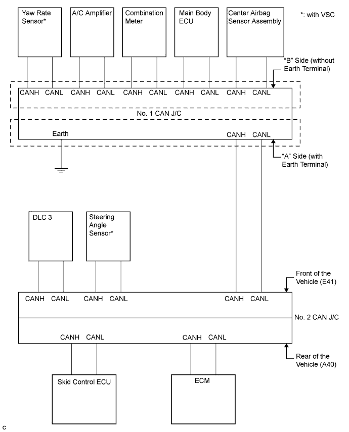
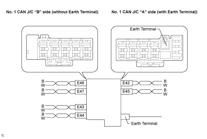
| CAN J/C connectors ("A" side, with earth terminal) | Connector Color | Wire Color (CAN-H) | Wire Color (CAN-L) |
| Airbag Sensor Assembly Center (E45) | Black | B | W |
| CAN J/C connectors ("B" side, with earth terminal) | Connector Color | Wire Color (CAN-H) | Wire Color (CAN-L) |
| Yaw Rate Sensor (E46)* | Blue | B | W |
| A/C Amplifier (E47) | Gray | B | W |
| Main Body ECU (E44) | Black | B | W |
| Symptom | Proceed to |
| The resistance is still below 54 Ω when all the specified connectors are disconnected. (There are no shorts in the branch wires.) | A |
| The resistance becomes normal (between 54 and 69 Ω) when a connector is disconnected. (There is a short in one or more of the branch wires.) | B |
When there is a short in one or more of the branch wires:
Reconnect all of the connectors to the No. 1 CAN J/C, except for the one that was disconnected last (the short-circuited bus wire). Check that the resistance shown on the tester is normal (between 54 and 69 Ω) to confirm that there is a short in one branch wire only.
|
| ||||
| A | |
|
| 4.CHECK FOR SHORT IN CAN BUS WIRES (COMBINATION METER MAIN BUS WIRE) |
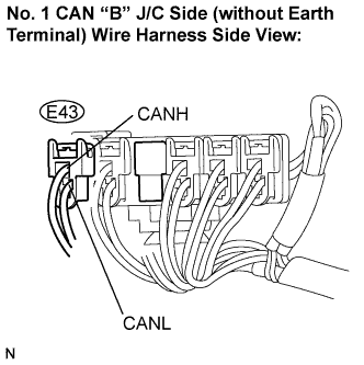 |
Disconnect the combination meter main bus wire connector (E43) from the No. 1 CAN J/C "B" side (without earth terminal).
|
Measure the resistance according to the value(s) in the table below.
| Tester Connection | Condition | Specified Value |
| E10-6 (CANH) - E10-14 (CANL) | Ignition switch off | 108 to 132 Ω |
|
| ||||
| OK | |
|
| 5.RECONNECT CONNECTOR |
Reconnect the combination meter main bus wire connector (E43) to the No. 1 CAN J/C "A" side (with earth terminal).
| NEXT | |
|
| 6.CHECK FOR SHORT IN CAN BUS WIRES (COMBINATION METER) |
|
Disconnect the combination meter connector (F1).
Measure the resistance according to the value(s) in the table below.
| Tester Connection | Condition | Specified Value |
| E10-6 (CANH) - E10-14 (CANL) | Ignition switch off | 108 to 132 Ω |
|
| ||||
| OK | ||
 | ||
| ||
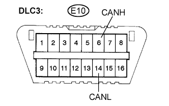
| 7.CHECK FOR SHORT IN CAN BUS WIRES (NO. 1 CAN J/C - NO. 2 CAN J/C) |
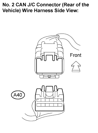  |
Disconnect the No. 2 CAN J/C connector (A40).
Measure the resistance according to the value(s) in the table below.
| Tester Connection | Condition | Specified Value |
| E10-6 (CANH) - E10-14 (CANL) | Ignition switch off | 108 to 132 Ω |
|
| ||||
| NG | |
|
| 8.CHECK FOR SHORT IN CAN BUS WIRES (STEERING ANGLE SENSOR BRANCH WIRE) |
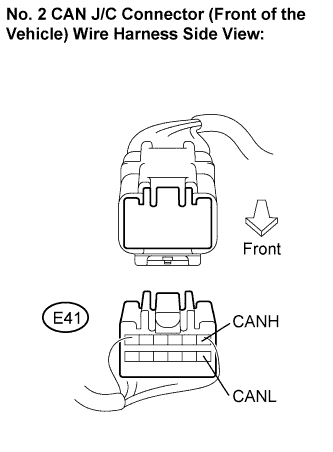 |
Reconnect the No. 2 CAN J/C connector (A40).
Disconnect the No. 2 CAN J/C connector (E41).
Measure the resistance according to the value(s) in the table below.
| Tester Connection | Condition | Specified Value |
| E41-1 (CANH) - E41-7 (CANL) | Ignition switch off | 1 MΩ or higher |
|
| ||||
| OK | |
|
| 9.CHECK FOR SHORT IN CAN BUS WIRES (NO. 1 CAN J/C - NO. 2 CAN J/C) |
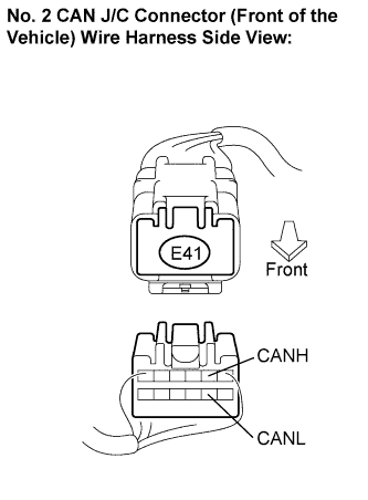 |
Disconnect the No. 2 CAN J/C connector (E41).
Measure the resistance according to the value(s) in the table below.
| Tester Connection | Condition | Specified Value |
| E41-2 (CANH) - E41-8 (CANL) | Ignition switch off | 1 MΩ or higher |
|
| ||||
| OK | ||
| ||
| ||
| 10.CHECK FOR SHORT IN CAN BUS WIRES (STEERING ANGLE SENSOR - NO. 2 CAN J/C) |
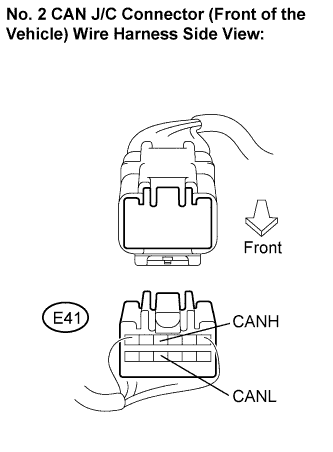 |
Disconnect the steering angle sensor connector (E17).
Measure the resistance according to the value(s) in the table below.
| Tester Connection | Condition | Specified Value |
| E41-4 (CANH) - E41-10 (CANL) | Ignition switch off | 1 MΩ or higher |
|
| ||||
| OK | ||
| ||
| ||
| 11.CHECK FOR SHORT IN CAN BUS WIRES (ECM MAIN BUS WIRE) |
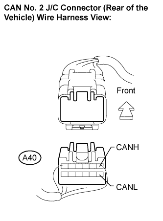 |
Disconnect the No. 2 CAN J/C connector (A40).
Measure the resistance according to the value(s) in the table below.
| Tester Connection | Condition | Specified Value |
| A40-1 (CANH) - A40-7 (CANL) | Ignition switch off | 1 MΩ or higher |
|
| ||||
| OK | |
|
| 12.CHECK FOR SHORT IN CAN BUS WIRES (SKID CONTROL ECU - NO. 2 CAN J/C) |
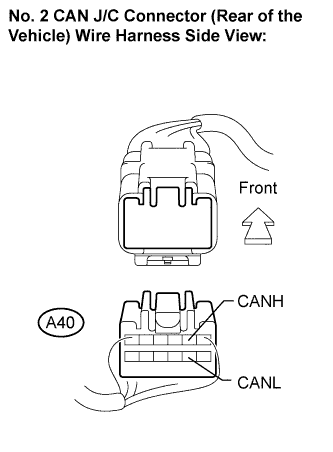 |
Disconnect the skid control ECU connector (A25 or A26).
Measure the resistance according to the value(s) in the table below.
| Tester Connection | Condition | Specified Value |
| A40-2 (CANH) - A40-8 (CANL) | Ignition switch off | 1 MΩ or higher |
|
| ||||
| NG | ||
| ||
| ||
| 13.CHECK FOR SHORT IN CAN BUS WIRES (ECM MAIN BUS WIRE) |
|
Disconnect the ECM connector (A24).
Measure the resistance according to the value(s) in the table below.
| Tester Connection | Condition | Specified Value |
| A40-1 (CANH) - A40-7 (CANL) | Ignition switch off | 1 MΩ or higher |
|
| ||||
| OK | ||
| ||
| ||
| 14.RECONNECT CONNECTOR |
Reconnect the connector for the short-circuited branch wire to the No. 1 CAN J/C (the connector that caused the bus wire resistance to become normal (between 54 and 69 Ω) when it was disconnected).
| NEXT | |
|
| 15.CHECK FOR SHORT IN CAN BUS WIRES |
|
Disconnect the connector that includes terminals CANH and CANL from the ECU (or sensor) to which the short-circuited branch wire is connected. (Click here)
Measure the resistance according to the value(s) in the table below.
| Tester Connection | Condition | Specified Value |
| E10-6 (CANH) - E10-14 (CANL) | Ignition switch off | 54 to 69 Ω |
|
| ||||
| OK | ||
| ||
| ||

