 |
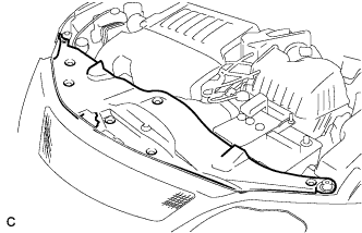
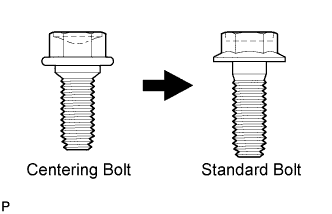
Remove the 7 clips and intake duct seal.
HOOD > ADJUSTMENT |
| 1. REMOVE COOL AIR INTAKE DUCT SEAL (for 2GR-FE) |
|
Remove the 7 clips and intake duct seal.
| 2. REMOVE FRONT BUMPER ASSEMBLY |
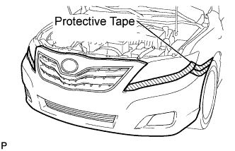 |
Put protective tape around the front bumper assembly.
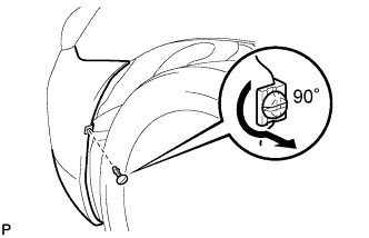 |
Using a screwdriver, turn the pin 90 degrees and remove the pin hold clip.
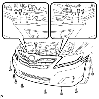 |
Remove the 8 screws, 2 clips, 2 radiator grille protectors and bolt.
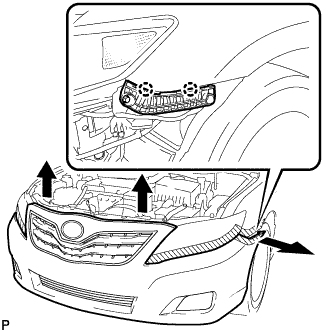 |
Disengage the 2 claws and disconnect the front bumper assembly as shown in the illustration.
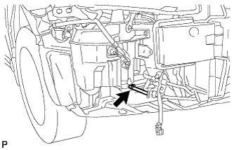
Disconnect each connector.
w/ TOYOTA Parking Assist-sensor System:
Disengage the clamp and disconnect the No. 1 ultrasonic sensor connector.
w/ Headlight Cleaner System:
Disconnect the headlight cleaner washer hose.
 |
Remove the front bumper assembly.
| 3. ADJUST HOOD SUB-ASSEMBLY |
Horizontally and vertically adjust the hood.
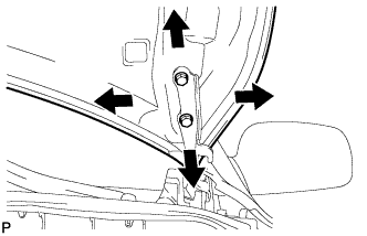 |
Loosen the 4 hinge bolts of the hood.
Adjust the clearance between the hood and front fender by moving the hood.
Tighten the 4 hinge bolts after the adjustment.
Adjust the height of the front end of the hood using the cushion rubber.
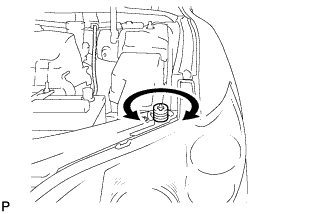 |
Adjust the cushion rubber so that the height of the hood and fender are aligned.
Adjust the hood lock.
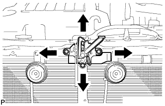 |
Loosen the 3 bolts.
Tighten the bolts after the adjustment.
Check that the striker can engage with the hood lock smoothly.
| 4. INSTALL FRONT BUMPER ASSEMBLY |
w/ Headlight Cleaner System:
|
Connect the headlight cleaner washer hose.
Connect each connector.
w/ TOYOTA Parking Assist-sensor System:
Connect the No. 1 ultrasonic sensor connector and engage the clamp.
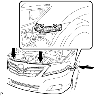 |
Engage the 2 claws.
|
Install the front bumper assembly with the 8 screws, 2 clips, 2 radiator grille protectors and bolt.
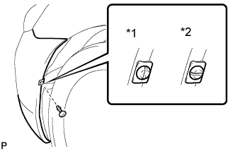 |
Install the pin hold clip.
|
Remove the applied protective tape on the front bumper assembly.
| 5. INSTALL COOL AIR INTAKE DUCT SEAL (for 2GR-FE) |
|
Install the intake duct seal with the 7 clips.
| 6. VEHICLE PREPARATION FOR FOG LIGHT AIM ADJUSTMENT |
Prepare the vehicle:
| 7. PREPARATION FOR FOG LIGHT AIMING |
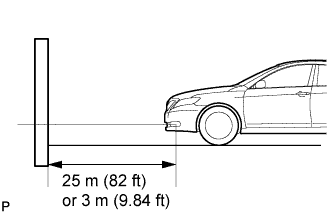 |
Prepare the vehicle:
Prepare a piece of thick white paper (approximately 2 m (6.6 ft) (height) x 4 m (13.1 ft) (width)) to use as a screen.
Draw a vertical line down the center of screen (V line).
Set the screen as shown in the illustration.
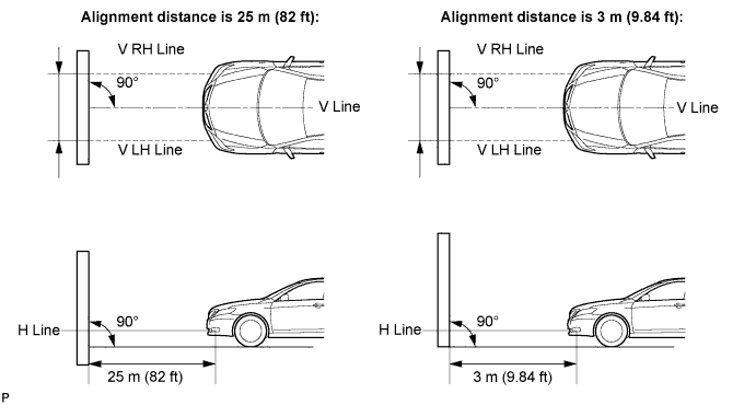
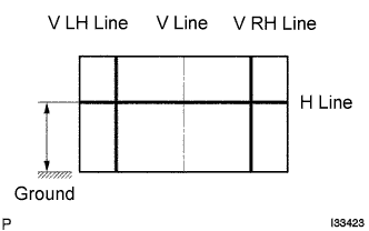 |
Draw base lines (H, V LH, and V RH lines) on the screen as shown in the illustration.
H Line (Fog light height):
Draw a horizontal line across the screen so that it passes through the center marks. The H line should be at the same height as the fog light bulb center marks of the low-beam fog lights.
V LH Line, V RH Line (Center mark position of left-hand (LH) and right-hand (RH) fog lights):
Draw two vertical lines so that they intersect the H line at each center mark.
| 8. FOG LIGHT AIMING INSPECTION |
Cover the fog light or disconnect the connector of the fog light on the opposite side to prevent light from the fog light that is not being inspected from affecting the fog light aiming inspection.
Start the engine.
Turn on the fog light and check if the cut off line falls within the specified area in the following illustration.
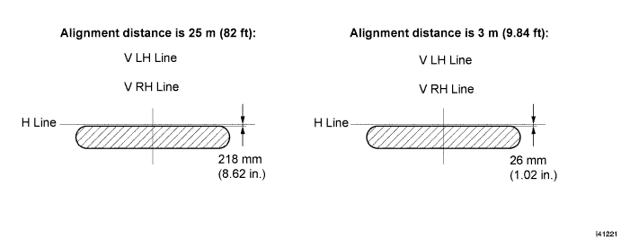
| 9. FOG LIGHT AIMING ADJUSTMENT |
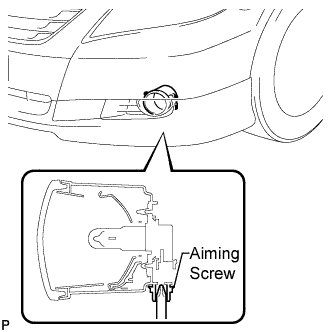 |
Adjust the aim vertically:
Adjust the aim of each fog light to the specified range by turning each aiming screw with a screwdriver.