Home › BRAKE › BRAKE CONTROL › VEHICLE STABILITY CONTROL SYSTEM

VEHICLE STABILITY CONTROL SYSTEM > TERMINALS OF ECU

for Preparation Click here


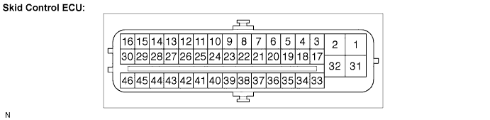
Terminal of ECU

F045080E06


Symbols (Terminal No.)
Terminal Description
GND2 (1)
Pump motor ground
BM (2)
Motor relay input
FR+ (3)
Front wheel speed RH signal (+) input
FL- (4)
Front wheel speed LH signal (-) input
RR+ (5)
Rear wheel speed RH signal (+) input
RL- (6)
Rear wheel speed LH signal (-) input
CANH (11)
CAN communication line H
SP1 (12)
Speed signal output for combination meter
D/G (13)
Diagnosis tester communication line
MRF (14)
Fail safe motor relay output
MR (15)
Motor relay output
FR- (17)
Front wheel speed RH signal (-) input
FL+ (18)
Front wheel speed LH signal (+) input
RR- (19)
Rear wheel speed RH signal (-) input
RL+ (20)
Rear wheel speed LH signal (+) input
TS (24)
Test mode (signal check) input
CANL (25)
CAN communication line L
STP (27)
Stop light switch input
+BS (31)
Solenoid relay power supply
GND1 (32)
Skid control ECU ground
WFSE (42)
WFSE input
R+ (45)
Power supply for motor relay
IG1 (46)
IG1 power supply

Terminal Inspection


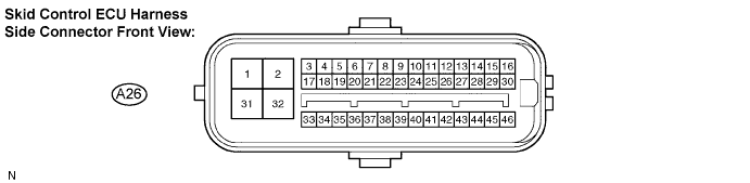
  1. Disconnect the connector and measure the voltage or resistance on the wire harness side.


    F049377E11

    HINT:
    Voltage cannot be measured with the connector connected to the skid control ECU because the connector is watertight.


    Standard:

    Symbols (Terminal No.)
    Wiring Color
    Terminal Description
    Condition
    Specified Condition
    GND2 (A26-1) - Body ground
    W-B - Body ground
    Pump motor ground
    Ignition switch off
    Below 1 Ω
    STP (A26-27) - Body ground
    P - Body ground
    Stop light switch input
    Stop light switch ON → OFF (Brake pedal depressed → released)
    8 to 14 V → Below 1.5 V
    +BS (A26-31) - Body ground
    L - Body ground
    Solenoid relay power supply
    Always
    10 to 14 V
    GND1 (A26-32) - Body ground
    W-B - Body ground
    Skid control ECU ground
    Always
    Below 1 Ω
    IG1 (A26-46) - Body ground
    P - Body ground
    IG1 power supply
    Ignition switch on (IG)
    10 to 14 V