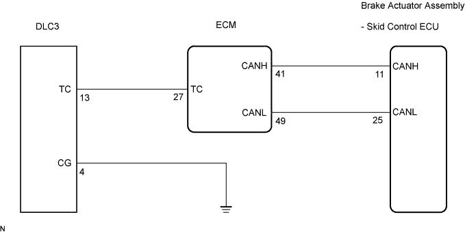
VEHICLE STABILITY CONTROL SYSTEM > TC and CG Terminal Circuit |
| 1.CHECK CAN COMMUNICATION SYSTEM |
Check if the CAN communication system DTC is output (Click here for LHD, or Click here for RHD).
| Condition | Proceed to |
| DTC is not output | A |
| DTC is output | B |
|
| ||||
| A | |
 |
| 2.INSPECT DLC3 |
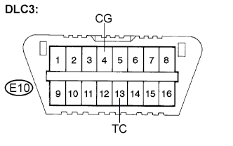 |
Turn the ignition switch to the ON position.
Measure the voltage according to the value(s) in the table below.
| Tester Connection | Condition | Specified Condition |
| E10-13 (TC) - E10-4 (CG) | Ignition switch ON | 10 to 14 V |
|
| ||||
| NG | |
|
| 3.CHECK HARNESS AND CONNECTOR (TC of DLC3 - ECM) |
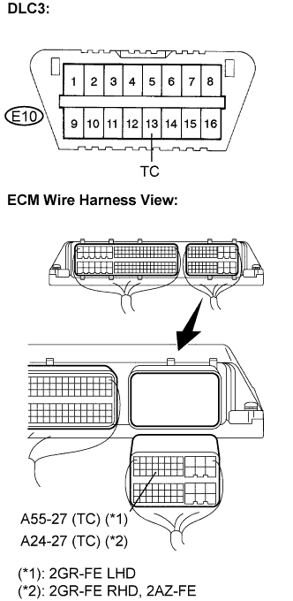 |
Turn the ignition switch off.
Disconnect the ECM connector.
Measure the resistance according to the value(s) in the table below.
| Tester Connection | Condition | Specified Condition |
| E10-13 (TC) - A55-27 (TC) | Always | Below 1 Ω |
| E10-13 (TC) - Body ground | Always | 10 kΩ or higher |
| Tester Connection | Condition | Specified Condition |
| E10-13 (TC) - A24-27 (TC) | Always | Below 1 Ω |
| E10-13 (TC) - Body ground | Always | 10 kΩ or higher |
| Tester Connection | Condition | Specified Condition |
| E10-13 (TC) - A24-27 (TC) | Always | Below 1 Ω |
| E10-13 (TC) - Body ground | Always | 10 kΩ or higher |
|
| ||||
| OK | |
|
| 4.CHECK HARNESS AND CONNECTOR (CG of DLC3 - BODY GROUND) |
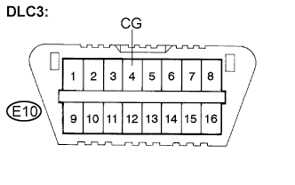 |
Measure the resistance according to the value(s) in the table below.
| Tester Connection | Condition | Specified Condition |
| E10-4 (CG) - Body ground | Always | Below 1 Ω |
|
| ||||
| OK | |
|
| 5.CHECK ECM (TC of DLC3 INPUT) |
|
Turn the ignition switch off.
Reconnect the ECM connector.
Using SST, connect terminals TC and CG of the DLC3.
Turn the ignition switch to the ON position.
Check that the check engine warning light is blinking.
| Condition | Proceed to |
| Check engine warning light is blinking | A |
| Check engine warning light is not blinking | B |
|
| ||||
| A | ||
 | ||
| ||

