 |
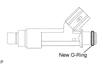
Apply a light coat of gasoline or spindle oil to new O-rings, then install one onto each fuel injector.
FUEL INJECTOR > INSTALLATION |
| 1. INSTALL FUEL INJECTOR ASSEMBLY |
|
Apply a light coat of gasoline or spindle oil to new O-rings, then install one onto each fuel injector.
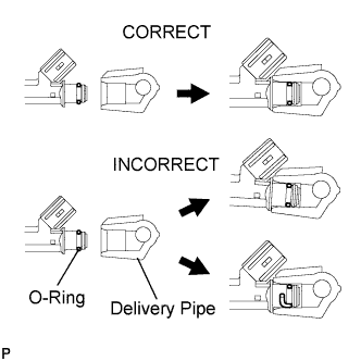 |
Apply a light coat of gasoline or spindle oil to the part of the fuel delivery pipe which comes into contact with the O-ring of the fuel injector.
Apply a light coat of gasoline or spindle oil to the O-ring again, then install the right and left fuel injectors onto the fuel delivery pipe.
Check that the fuel injector rotates smoothly. If the fuel injector does not rotate, replace the O-ring.
| 2. INSTALL FUEL DELIVERY PIPE WITH INJECTOR |
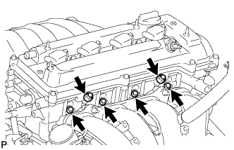 |
Install 4 new insulators into the cylinder head.
Install the 2 delivery pipe spacers onto the cylinder head.
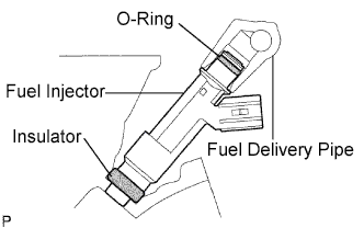 |
Install the fuel delivery pipe together with the 4 fuel injectors, then temporarily tighten the 2 bolts.
Check that the fuel injector rotates smoothly.
If the fuel injector does not rotate smoothly, replace the O-ring.
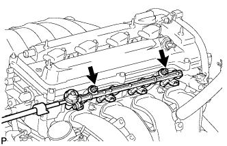 |
Tighten the 2 bolts to the specified torque.
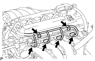 |
Connect the 4 fuel injector connectors.
Install the 2 wire harness clamps.
| 3. INSTALL NO. 2 VENTILATION HOSE |
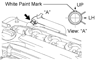 |
Connect the ventilation hose to the ventilation valve.
| 4. CONNECT FUEL TUBE SUB-ASSEMBLY |
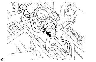 |
Install the fuel tube to the fuel hose clamp.
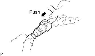 |
Push the fuel tube connector until it makes a "click" sound.
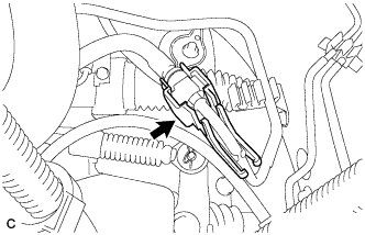 |
Install the No. 1 fuel pipe clamp.
| 5. INSTALL AIR CLEANER CAP SUB-ASSEMBLY |
Install the air cleaner filter element onto the air cleaner case.
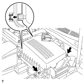 |
Insert the hinges. Install the air cleaner cap sub-assembly with the 2 bolts.
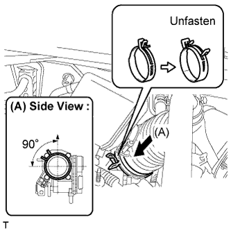 |
Align the matchmarks of the No. 1 air cleaner hose and throttle body, and then connect the air cleaner hose No. 1 to the throttle body and unfasten the No. 1 air cleaner hose clamp.
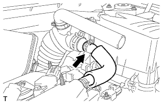 |
Connect the No. 2 ventilation hose to the air cleaner hose.
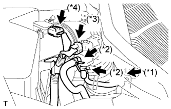 |
Connect the purge line hose to the clamp (*1).
Connect the 2 purge VSV vacuum hoses (*2).
Connect the purge VSV connector (*3).
Connect the mass air flow meter connector (*4).
| 6. CONNECT CABLE TO NEGATIVE BATTERY TERMINAL |
| 7. CHECK FOR FUEL LEAKS |
| 8. INSTALL NO. 1 ENGINE COVER SUB-ASSEMBLY |
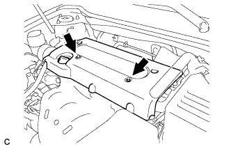 |
Install the engine cover with the 2 nuts.