Home › SUSPENSION & AXLE › SUSPENSION › REAR WHEEL ALIGNMENT

REAR WHEEL ALIGNMENT > ADJUSTMENT

for Preparation Click here


1. INSPECT TIRES
(Click here)


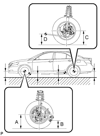
2. MEASURE VEHICLE HEIGHT


    C132408E01
  1. Bounce the vehicle up and down at the corners to stabilize the suspension. Inspect the vehicle height.

    Vehicle height:
    Model
    Front A - B
    Rear C - D
    ACV40L-AEANKW
    115 mm (4.53 in.)
    38 mm (1.50 in.)
    ACV40R-AEANKW
    115 mm (4.53 in.)
    38 mm (1.50 in.)
    ACV40L-AEMNKW
    117 mm (4.61 in.)
    42 mm (1.65 in.)
    ACV40R-AEMNKW
    117 mm (4.61 in.)
    42 mm (1.65 in.)
    GSV40L-AETGKW
    117 mm (4.61 in.)
    42 mm (1.65 in.)
    GSV40R-AETGKW
    117 mm (4.61 in.)
    42 mm (1.65 in.)

    Measuring points:
    A:
    Ground clearance of front wheel center
    B:
    Ground clearance of lower suspension arm No. 2 bushing set bolt center
    C:
    Ground clearance of rear wheel center
    D:
    Ground clearance of strut rod set bolt center

    NOTICE:
    1. Before inspecting the wheel alignment, adjust the vehicle height to the specified value.
    2. Be sure to perform measurement on a level surface.
    3. If it is necessary to go under the vehicle for measurement, confirm that the parking brake is applied and the vehicle is secured with chocks.
3. INSPECT TOE-IN


    C132438E02
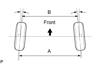
  1. Bounce the vehicle up and down at the corners to stabilize the suspension. Inspect the toe-in.

    Toe-in:
    Toe-in
    (total)
    -
    A - B:
    4 +- 2 mm (0.16 +- 0.08 in.)

    If the toe-in is not within the specified range, inspect the suspension parts and replace them if necessary.


4. ADJUST TOE-IN


    C132497
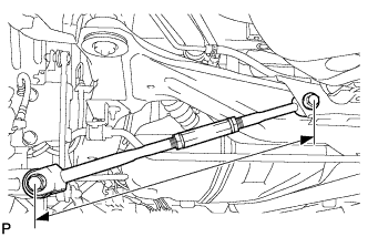
  1. Measure the lengths of the right and left rear No. 2 suspension arms.

    Difference in the length between the right and left rear No. 2 suspension arms:
    1.5 mm (0.06 in.) or less

    If the left-right difference is larger than 1.5 mm (0.06 in.), adjust it by following the procedures below.


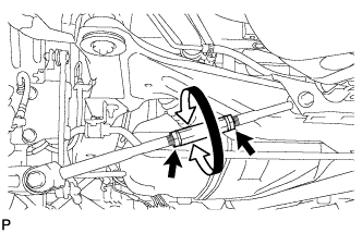
    C132498
  1. Loosen the lock nuts.

  1. Turn the right and left adjusting tubes by an equal amount to adjust toe-in.

    HINT:
    1. Try to adjust toe-in to the center of the specified range.
    2. One turn of each adjusting tube will adjust toe-in by approximately 10.8 mm (0.425 in.).

  1. Tighten the lock nuts.

    Torque:
    56 N*m{ 571 kgf*cm , 41 ft.*lbf }


5. INSPECT CAMBER

Camber:
Camber
Right-left difference
-1°00' +-45' (-1.00° +-0.75°)
45' (0.75°) or less

HINT:
Camber is not adjustable. If the measurement is not within the specification, inspect the suspension parts for damage and/or wear, and replace them if necessary.