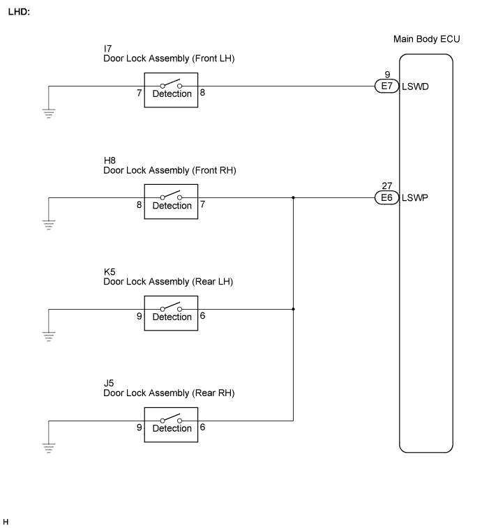
LIGHTING SYSTEM > Door LOCK Position Circuit |
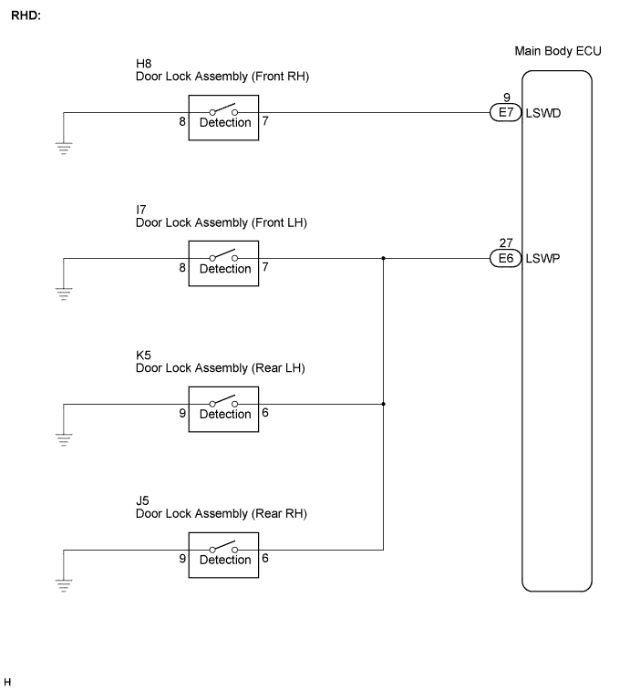
| 1.READ VALUE USING INTELLIGENT TESTER |
Connect the intelligent tester to the DLC3.
Turn the ignition switch to the ON position and turn the intelligent tester main switch on.
Select the items below in the DATA LIST, and read the display on the intelligent tester.
| Item | Measurement Item / Display (Range) | Normal Condition | Diagnostic Note |
| D-Door Lock Pos SW | Driver side door lock position switch signal / ON or OFF | ON: Driver side door is unlocked OFF: Driver side door is locked | - |
| P-Door Lock Pos SW | Passenger side door lock position switch signal / ON or OFF | ON: Passenger side door or rear LH door or rear RH door is unlocked OFF: Passenger side door and rear LH door and rear RH door doors are locked | - |
|
| ||||
| OK | ||
 | ||
| ||
