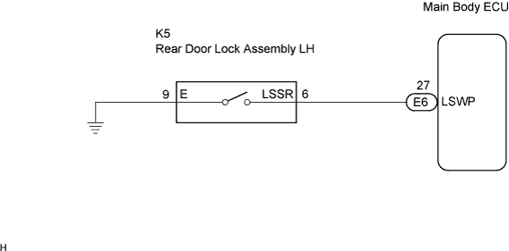
POWER DOOR LOCK CONTROL SYSTEM > Rear Door UNLOCK Detection Switch LH Circuit |
| 1.INSPECT REAR DOOR LOCK ASSEMBLY (UNLOCK DETECTION SWITCH) |
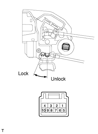 |
Remove the rear door lock assembly LH.
Measure the resistance according to the value(s) in the table below.
| Tester Connection | Measurement Condition | Door Lock Condition | Specified Condition |
| 6 - 9 | Battery positive (+) → Terminal 4 Battery negative (-) → Terminal 1 | Lock | 10 kΩ or higher |
| 6 - 9 | Battery positive (+) → Terminal 1 Battery negative (-) → Terminal 4 | Unlock | Below 1 Ω |
|
| ||||
| OK | |
 |
| 2.CHECK WIRE HARNESS (REAR DOOR LOCK ASSEMBLY - MAIN BODY ECU) |
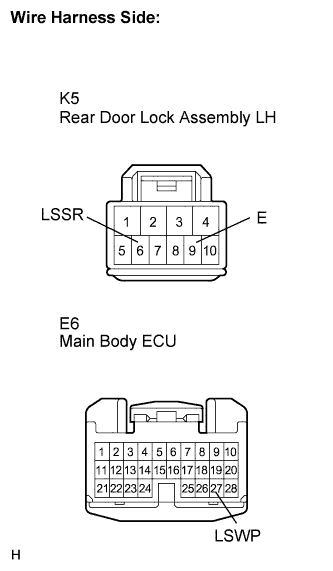 |
Disconnect the rear door lock assembly LH connector.
Disconnect the ECU connector.
Measure the resistance according to the value(s) in the table below.
| Tester Connection (Symbols) | Condition | Specified Condition |
| K5-6 (LSSR) - E6-27 (LSWP) | Always | Below 1 Ω |
| K5-6 (LSSR) - Body ground | Always | 10 kΩ or higher |
| K5-9 (E) - Body ground | Always | Below 1 Ω |
|
| ||||
| OK | ||
 | ||
| ||
