POWER WINDOW CONTROL SYSTEM (for Models with Jam Protection Function on Driver Door Window Only) > DIAGNOSIS SYSTEM |
| DESCRIPTION |
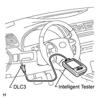
The power window control system data can be read from the Data Link Connector 3 (DLC3) of the vehicle. When the system seems to be malfunctioning, use the intelligent tester to check for malfunctions and perform repairs.
| CHECK DLC3 |
|
 |
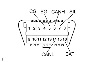
The ECU uses ISO 15765-4 communication. The terminal arrangement of the DLC3 complies with ISO 15031-3 and matches the ISO 15765-4 format.
| Symbols (Terminal No.) | Terminal Description | Condition | Specified Condition |
| SIL (7) - SG (5) | Bus "+" line | During transmission | Pulse generation |
| CG (4) - Body ground | Chassis ground | Always | Below 1 Ω |
| SG (5) - Body ground | Signal ground | Always | Below 1 Ω |
| BAT (16) - Body ground | Battery positive | Always | 10 to 14 V |
| CANH (6) - CANL (14) | CAN bus line | Ignition switch OFF* | 54 to 69 Ω |
| CANH (6) - CG (4) | HIGH-level CAN bus line | Ignition switch OFF* | 200 Ω or more |
| CANL (14) - CG (4) | LOW-level CAN bus line | Ignition switch OFF* | 200 Ω or more |
| CANH (6) - BAT (16) | HIGH-level CAN bus line | Ignition switch OFF* | 6 kΩ or more |
| CANL (14) - BAT (16) | LOW-level CAN bus line | Ignition switch OFF* | 6 kΩ or more |
| CHECK DIAGNOSIS (WITH JAM PROTECTION) |
 |
Turn the ignition switch ON.
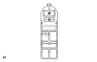
Manually operate the power window master switch or power window switch on each door.
Check the blinking pattern of the AUTO light as shown in the illustration.
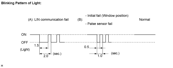
If pattern (A) is displayed, check wire harness or power window ECU.
If pattern (B) is displayed, check power window regulator motor or power window ECU.
If the normal pattern is displayed, replace the power window regulator master switch.