 |
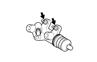
Install the clutch release cylinder and clutch line bracket with the 2 bolts.
- Torque:
- 12 N*m{ 120 kgf*cm , 9 ft.*lbf }
CLUTCH RELEASE CYLINDER > INSTALLATION |
| 1. INSTALL CLUTCH RELEASE CYLINDER ASSEMBLY |
|
Install the clutch release cylinder and clutch line bracket with the 2 bolts.
| 2. INSTALL CLUTCH ACCUMULATOR ASSEMBLY |
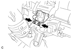 |
Install the clutch accumulator assembly with the 2 nuts.
| 3. CONNECT CLUTCH LINE |
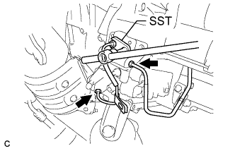 |
Using SST, connect the clutch lines to the clutch accumulator assembly.
| 4. INSTALL RELEASE CYLINDER HEAT INSULATOR |
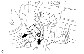 |
Install the release cylinder heat insulator with the 2 bolts.
| 5. INSTALL CLUTCH ACCUMULATOR BRACKET |
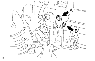 |
Install the clutch accumulator bracket with the 2 bolts.
| 6. BLEED CLUTCH LINE |
Fill the brake reservoir with brake fluid and bleed the clutch system.
| 7. CHECK FOR BRAKE FLUID LEAKAGE |
| 8. INSTALL AIR CLEANER CASE SUB-ASSEMBLY |
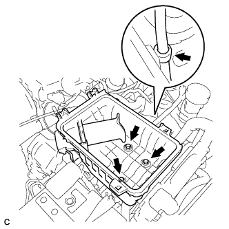 |
Install the air cleaner case with the 3 bolts.
Connect the hose clamp.
| 9. INSTALL AIR CLEANER CAP SUB-ASSEMBLY |
Install the air cleaner filter element onto the air cleaner case.
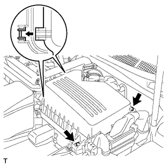 |
Insert the hinges. Install the air cleaner cap sub-assembly with the 2 bolts.
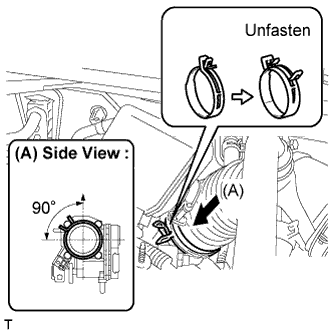 |
Align the matchmarks of the No. 1 air cleaner hose and throttle body, and then connect the air cleaner hose No. 1 to the throttle body and unfasten the No. 1 air cleaner hose clamp.
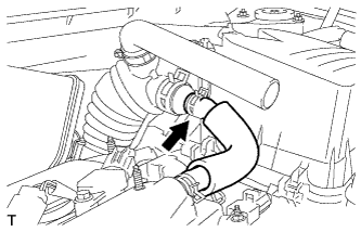 |
Connect the No. 2 ventilation hose to the air cleaner hose.
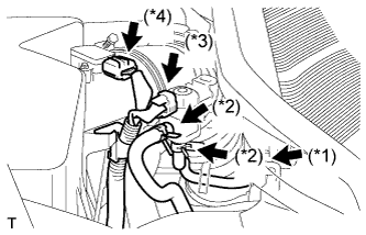 |
Connect the purge line hose to the clamp (*1).
Connect the 2 purge VSV vacuum hoses (*2).
Connect the purge VSV connector (*3).
Connect the mass air flow meter connector (*4).
| 10. INSTALL AIR CLEANER INLET ASSEMBLY |
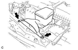 |
Install the air cleaner inlet with the 2 bolts.
| 11. CHECK FLUID LEVEL IN RESERVOIR |
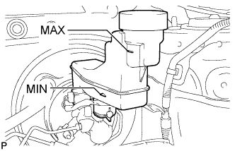 |
Check the fluid level.
If brake fluid level is lowered, check for leakage and inspect the disc brake pad. If necessary, refill the reservoir with brake fluid after repair and replacement.
| 12. CONNECT CABLE TO NEGATIVE BATTERY TERMINAL |