 |
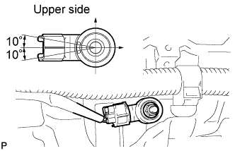
Install the knock sensor with the nut.
- Torque:
- 20 N*m{ 204 kgf*cm , 15 ft.*lbf }
- NOTICE:
- Make sure that the knock sensor is in the correct position.
KNOCK SENSOR > INSTALLATION |
| 1. INSTALL KNOCK SENSOR |
|
Install the knock sensor with the nut.
Connect the knock sensor connector.
| 2. INSTALL INTAKE MANIFOLD |
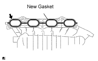 |
Install a new gasket into the intake manifold.
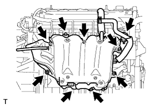 |
Install the intake manifold with the 5 bolts and 2 nuts.
Fit the union to check valve hose into the vacuum hose clamp.
Install the wire harness clamp.
Connect the camshaft timing oil control valve connector.
Connect the union to check valve hose to the brake booster.
| 3. CONNECT FUEL TUBE |
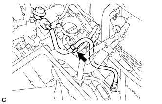 |
Install the fuel tube to the fuel hose clamp.
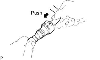 |
Push the fuel tube connector until it makes a "click" sound.
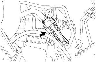 |
Install the No. 1 fuel pipe clamp.
| 4. INSTALL FUEL DELIVERY PIPE WITH INJECTOR |
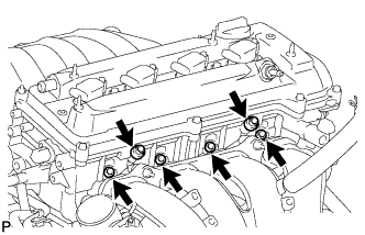 |
Install 4 new insulators into the cylinder head.
Install the 2 delivery pipe spacers onto the cylinder head.
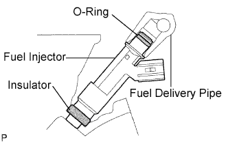 |
Install the fuel delivery pipe together with the 4 fuel injectors, then temporarily tighten the 2 bolts.
Check that the fuel injector rotates smoothly.
If the fuel injector does not rotate smoothly, replace the O-ring.
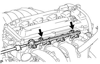 |
Tighten the 2 bolts to the specified torque.
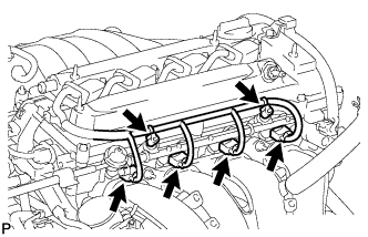 |
Connect the 4 fuel injector connectors.
Install the 2 wire harness clamps.
| 5. INSTALL THROTTLE BODY |
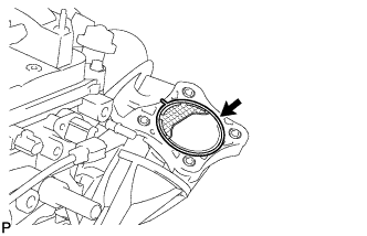 |
Install a new gasket onto the intake manifold.
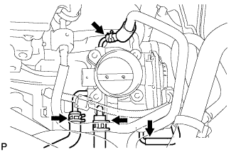 |
Connect the purge line hose to the throttle body.
Connect the water by-pass hose to the throttle body.
Connect the No. 2 water by-pass hose to the throttle body.
Connect the No. 1 throttle body hose to the throttle body.
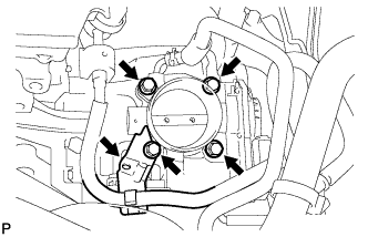 |
Install the throttle body and fuel pipe clamp with the 4 bolts.
Connect the fuel tube into the clamp.
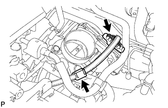 |
Connect the throttle position sensor connector.
Connect the wire harness clamp.
| 6. INSTALL AIR CLEANER CASE SUB-ASSEMBLY |
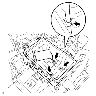 |
Install the air cleaner case with the 3 bolts.
Connect the hose clamp.
| 7. INSTALL AIR CLEANER CAP SUB-ASSEMBLY |
Install the air cleaner filter element onto the air cleaner case.
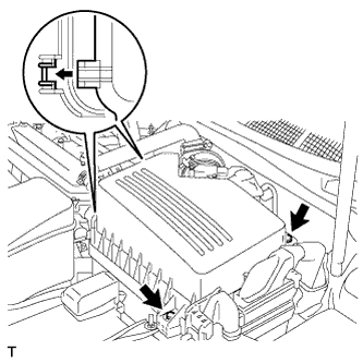 |
Insert the hinges. Install the air cleaner cap sub-assembly with the 2 bolts.
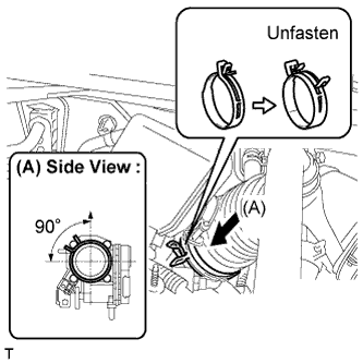 |
Align the matchmarks of the No. 1 air cleaner hose and throttle body, and then connect the air cleaner hose No. 1 to the throttle body and unfasten the No. 1 air cleaner hose clamp.
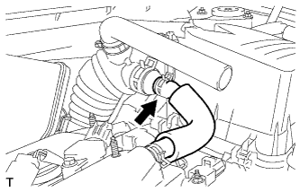 |
Connect the No. 2 ventilation hose to the air cleaner hose.
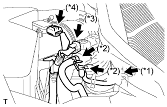 |
Connect the purge line hose to the clamp (*1).
Connect the 2 purge VSV vacuum hoses (*2).
Connect the purge VSV connector (*3).
Connect the mass air flow meter connector (*4).
| 8. CONNECT CABLE TO NEGATIVE BATTERY TERMINAL |
| 9. ADD ENGINE COOLANT |
Close the radiator drain cock plug and 2 cylinder block drain cock plugs.
Slowly fill the radiator with TOYOTA Super Long Life Coolant (SLLC).
Slowly pour coolant into the radiator reservoir tank until it reaches the FULL line.
Press the inlet and outlet radiator hoses several times by hand, and then check the level of the coolant.
If the coolant level is low, add coolant.
Install the radiator cap sub-assembly and reservoir tank cap.
Start the engine, and warm it up.
Stop the engine, and wait until the engine coolant cools down.
Add engine coolant to the FULL line on the radiator reservoir.
| 10. CHECK FOR ENGINE COOLANT LEAKS |
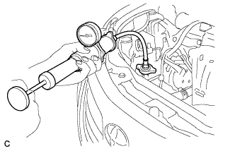 |
Fill the radiator with coolant and attach a radiator cap tester.
Warm up the engine.
Using a radiator cap tester, increase the pressure inside the radiator to 118 kPa (1.2 kgf*cm, 17 psi), and check that the pressure does not drop.
If the pressure drops, check the hoses, radiator and water pump for leaks. If no external leaks are found, check the heater core, cylinder block and cylinder head.
| 11. CHECK FOR FUEL LEAKS |
| 12. INSTALL NO. 1 ENGINE COVER SUB-ASSEMBLY |
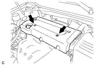 |
Install the engine cover with the 2 nuts.
| 13. INSTALL OUTER COWL TOP PANEL SUB-ASSEMBLY |
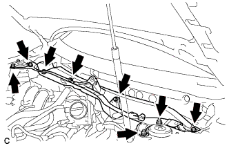 |
Install the outer cowl top panel sub-assembly with the 4 bolts and 4 nuts.
| 14. INSTALL WINDSHIELD WIPER MOTOR AND LINK |
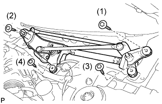 |
Install the windshield wiper motor and link assembly with the 4 bolts.
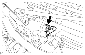 |
Connect the connector.
| 15. INSTALL COWL TOP VENTILATOR LOUVER SUB-ASSEMBLY |
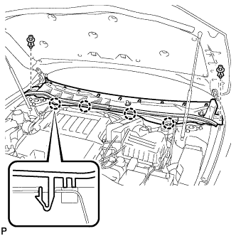 |
Engage the 4 claws and install the cowl top ventilator louver sub-assembly.
Install the 2 clips.
| 16. INSTALL FRONT FENDER TO COWL SIDE SEAL RH |
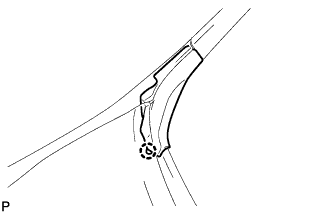 |
Engage the claw and install the front fender to cowl side seal RH.
| 17. INSTALL FRONT FENDER TO COWL SIDE SEAL LH |
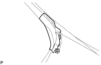 |
Engage the claw and install the front fender to cowl side seal LH.
| 18. INSTALL WINDSHIELD WIPER ARM AND BLADE ASSEMBLY LH |
Operate the wiper and stop the windshield wiper motor at the automatic stop position.
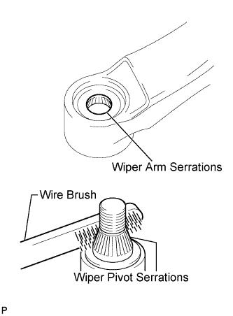 |
Clean the wiper arm serrations.
When reinstalling:
Clean the wiper pivot serrations with a wire brush.
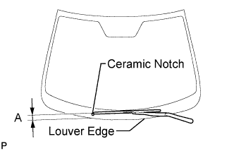 |
Install the front wiper arm and blade assembly LH with the nut to the position shown in the illustration.
| Area | Measurement |
| A | 37 to 52 mm (1.46 to 2.05 in.) |
| 19. INSTALL WINDSHIELD WIPER ARM AND BLADE ASSEMBLY RH |
Operate the wiper and stop the windshield wiper motor at the automatic stop position.
|
Clean the wiper arm serrations.
When reinstalling:
Clean the wiper pivot serrations with a wire brush.
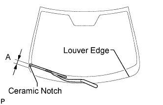 |
Install the front wiper arm and blade assembly RH with the nut to the position shown in the illustration.
| Area | Measurement |
| A | 23 to 38 mm (0.90 to 1.49 in.) |
Operate the front wipers while spraying washer fluid on the windshield glass. Make sure that the front wipers function properly and the wipers do not come into contact with the vehicle body.