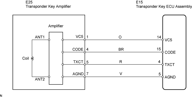
DTC B2784 Antenna Coil Open / Short |
| DTC No. | DTC Detection Condition | Trouble Area |
| B2784 | Antenna coil is open/shorted |
|
| 1.READ VALUE USING INTELLIGENT TESTER |
Connect the intelligent tester to the DLC3.
Turn the ignition switch to the ON position and turn the intelligent tester on.
Select Antenna Coil Status in the DATA LIST and read the value displayed on the intelligent tester.
| Tester Display | Measurement Item/Range | Normal Condition | Diagnostic Note |
| Antenna Coil Status | Transponder key amplifier coil condition/NORMAL or FAIL | NORMAL: Antenna coil is normal FAIL: Antenna coil is malfunctioning | - |
|
| ||||
| NG | |
 |
| 2.CHECK HARNESS AND CONNECTOR (TRANSPONDER KEY ECU - TRANSPONDER KEY AMPLIFIER) |
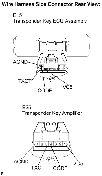 |
Disconnect the E15 ECU and E25 amplifier connectors.
Measure the resistance according to the value(s) in the table below.
| Tester Connection | Condition | Specified Condition |
| E15-4 (TXCT) - E25-5 (TXCT) | Always | Below 1 Ω |
| E15-5 (AGND) - E25-7 (AGND) | ||
| E15-14 (VC5) - E25-1 (VC5) | ||
| E15-15 (CODE) - E25-4 (CODE) | ||
| E15-4 (TXCT) - Body ground | 10 kΩ or higher | |
| E15-5 (AGND) - Body ground | ||
| E15-14 (VC5) - Body ground | ||
| E15-15 (CODE) - Body ground |
|
| ||||
| OK | |
|
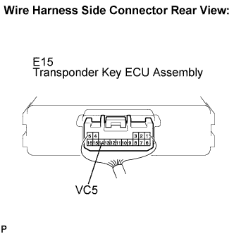
| 3.INSPECT TRANSPONDER KEY ECU ASSEMBLY (TRANSPONDER KEY AMPLIFIER POWER SOURCE) |
 |
Reconnect the E15 ECU and E25 amplifier connectors.
Measure the voltage according to the value(s) in the table below.
| Tester Connection | Condition | Specified Condition |
| E15-14 (VC5) - Body ground | No key is in ignition key cylinder | Below 1 V |
| Key is in ignition key cylinder | 4.6 to 5.4 V |
|
| ||||
| OK | |
|
| 4.INSPECT TRANSPONDER KEY ECU ASSEMBLY (TRANSPONDER KEY AMPLIFIER GROUND) |
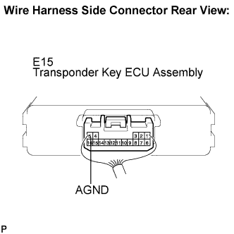 |
Measure the resistance according to the value(s) in the table below.
| Tester Connection | Condition | Specified Condition |
| E15-5 (AGND) - Body ground | Always | Below 1 Ω |
|
| ||||
| OK | ||
 | ||
| ||
