 |
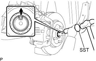
Using SST and a hammer, release the staked part of the front axle hub nut.
- SST
- 09930-00010
- NOTICE:
- Loosen the staked part of the nut completely, otherwise the thread of the drive shaft may be damaged.
FRONT DRIVE SHAFT > REMOVAL |
| 1. DRAIN AUTOMATIC TRANSAXLE FLUID (for Automatic Transaxle) |
for 2GR-FE: Click here
for 2AZ-FE: Click here
| 2. DRAIN MANUAL TRANSAXLE OIL (for Manual Transaxle) |
Remove the filler plug and the gasket.
Remove the drain plug and gasket, and drain the manual transaxle oil.
Install a new gasket and the drain plug.
| 3. REMOVE FRONT WHEEL |
| 4. REMOVE FRONT AXLE HUB NUT |
|
Using SST and a hammer, release the staked part of the front axle hub nut.
While applying the brakes, remove the front axle hub nut.
| 5. SEPARATE FRONT STABILIZER LINK ASSEMBLY |
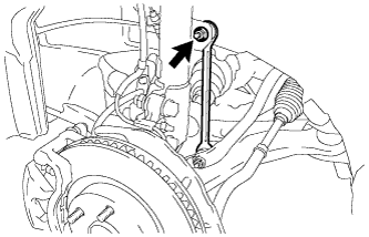 |
Remove the nut and separate the front stabilizer link assembly.
| 6. SEPARATE FRONT SPEED SENSOR |
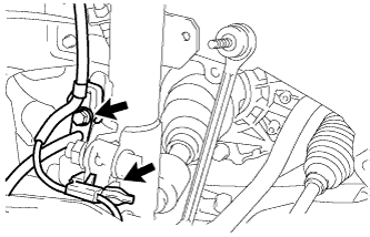 |
Remove the bolt and clip, and separate the speed sensor wire and flexible hose from the shock absorber.
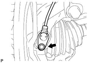 |
Remove the bolt and separate the speed sensor from the steering knuckle.
| 7. SEPARATE TIE ROD END SUB-ASSEMBLY |
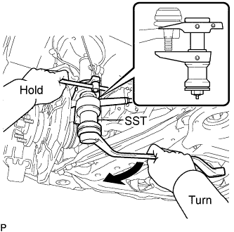 |
Remove the cotter pin and nut.
Using SST, separate the tie rod end sub-assembly from the steering knuckle.
| 8. SEPARATE FRONT SUSPENSION LOWER NO. 1 ARM |
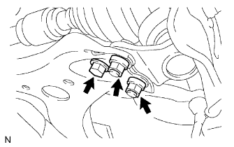 |
Remove the bolt and 2 nuts, and separate the front suspension lower No. 1 arm from the lower ball joint.
| 9. SEPARATE FRONT AXLE ASSEMBLY |
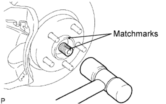 |
Put matchmarks on the front drive shaft assembly and the axle hub.
Using a plastic hammer, separate the front drive shaft assembly from the front axle assembly.
| 10. REMOVE FRONT DRIVE SHAFT ASSEMBLY LH |
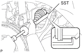 |
Using SST, remove the front drive shaft assembly LH.
| 11. REMOVE FRONT DRIVE SHAFT ASSEMBLY RH |
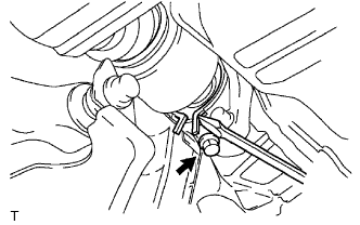 |
Using a screwdriver, remove the bearing bracket hole snap ring.
Remove the bolt and front drive shaft assembly RH from the drive shaft bearing bracket.
| 12. SECURE FRONT AXLE HUB SUB-ASSEMBLY |
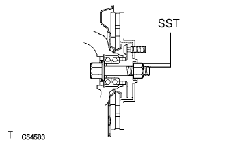 |
Secure the front axle hub bearing.
| 13. INSPECT FRONT DRIVE SHAFT ASSEMBLY |
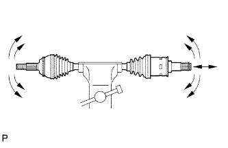 |
Check that there is no excessive play in the outboard joint.
Check that the inboard joint slides smoothly in the thrust direction.
Check that there is no excessive play in the radial directions of the inboard joint.
Check the boots for damage.