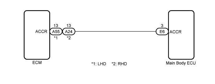
DTC B2276 ACCR Signal Circuit Malfunction |
| DTC No. | DTC Detection Condition | Trouble Area |
| B2276 | ACCR output circuit inside main body ECU or other related circuit is malfunctioning |
|
| 1.CHECK DTC OUTPUT |
Clear the DTCs (Click here).
Check for DTCs again.
|
| ||||
| OK | ||
 | ||
| ||
| 2.CHECK WIRE HARNESS (MAIN BODY ECU - ECM) |
Disconnect the E6 ECU connector.
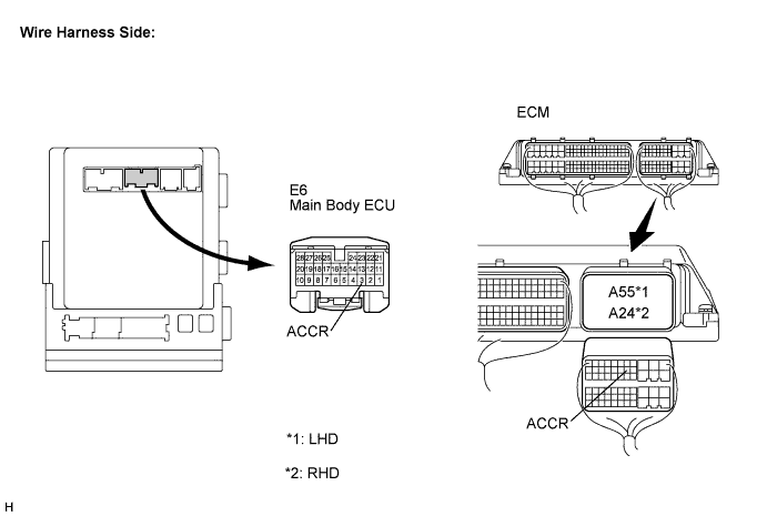
Disconnect the A55*1 or A24*2 ECM connector.
Measure the resistance according to the value(s) in the table below.
| Tester Connection | Condition | Specified Condition |
| E6-3 (ACCR) - A55-13 (ACCR)*1 E6-3 (ACCR) - A24-13 (ACCR)*2 | Always | Below 1 Ω |
| E6-3 (ACCR) - Body ground | Always | 10 kΩ or higher |
|
| ||||
| OK | |
 |
| 3.INSPECT MAIN BODY ECU |
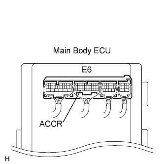 |
Reconnect the connectors.
Measure the voltage according to the value(s) in the table below.
| Tester Connection | Condition | Specified Condition |
| E6-3 (ACCR) - Body ground | Brake pedal depressed, shift P position, engine switch is pushed once → on (IG) | 0.1 to 0.8 V → output voltage at terminal AM1 or AM2 is -2 V or more. |
|
| ||||
| OK | |
|
| 4.CHECK MAIN BODY ECU OPERATION |
After replacing the main body ECU with a normally functioning ECU, check that the engine starts.
|
| ||||
| OK | ||
| ||
| ||

