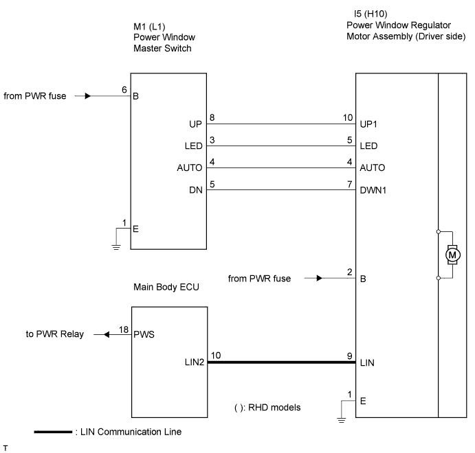
DTC B2312 Driver Side Door Master Switch Malfunction |
| DTC No. | DTC Detection Condition | Trouble Area |
| B2312 | The power window regulator master switch is stuck |
|
| 1.READ VALUE USING INTELLIGENT TESTER |
Using the data list to check the function of the power window power window ECU (Power window regulator motor).
| Item | Measurement Item/Display (Range) | Normal Condition | Diagnostic Note |
| D Door Auto SW | Driver door power window auto switch signal/ON or OFF | ON: Driver door power window auto switch operates OFF: Driver door power window auto switch does not operate | - |
| D Door Up SW | Driver door power window manual up switch signal/ON or OFF | ON: Driver door power window manual up switch operates OFF: Driver door power window manual up switch does not operate | - |
| D Door Down SW | Driver door power window manual down switch signal/ON or OFF | ON: Driver door power window manual down switch operates OFF: Driver door power window manual down switch does not operate | - |
|
| ||||
| NG | |
 |
| 2.INSPECT POWER WINDOW REGULATOR MASTER SWITCH ASSEMBLY |
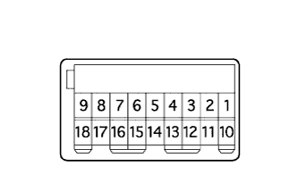 |
Measure the resistance according to the value(s) in the table below.
| Tester Connection | Condition | Specified Condition |
| 8 (UP) - 1 (E) - 4 (AUTO) | Auto UP | Below 1 Ω |
| 5 (DN) - 6 (B) | Auto UP | Below 1 Ω |
| 8 (UP) - 1 (E) | Manual UP | Below 1 Ω |
| 5 (DN) - 6 (B) | Manual UP | Below 1 Ω |
| 8 (UP) - 5 (DN) - 6 (B) | OFF | Below 1 Ω |
| 5 (DN) - 1 (E) | Manual DOWN | Below 1 Ω |
| 8 (UP) - 6 (B) | Manual DOWN | Below 1 Ω |
| 4 (AUTO) - 5 (DN) - 1 (E) | Auto DOWN | Below 1 Ω |
| 8 (UP) - 6 (B) | Auto DOWN | Below 1 Ω |
|
| ||||
| OK | |
|
| 3.CHECK WIRE HARNESS (WINDOW REGULATOR MASTER SWITCH - WINDOW REGULATOR MOTOR) |
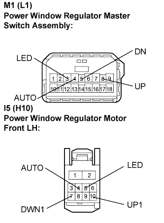 |
Disconnect the M1 (L1) and I5 (H10) connectors.
Measure the resistance according to the value(s) in the table below.
( ): RHD models
| Tester Connection | Condition | Specified Condition |
| M1-8 (UP) - I5-10 (UP1) | Always | Below 1 Ω |
| M1-3 (LED) - I5-5 (LED) | Always | Below 1 Ω |
| M1-4 (AUTO) - I5-4 (AUTO) | Always | Below 1 Ω |
| M1-5 (DN) - I5-7 (DWN1) | Always | Below 1 Ω |
| M1-8 (UP) - Body ground | Always | 10 kΩ or higher |
| M1-3 (LED) - Body ground | Always | 10 kΩ or higher |
| M1-4 (AUTO) - Body ground | Always | 10 kΩ or higher |
| M1-5 (DN) - Body ground | Always | 10 kΩ or higher |
| Tester Connection | Condition | Specified Condition |
| L1-8 (UP) - H10-10 (UP1) | Always | Below 1 Ω |
| L1-3 (LED) - H10-5 (LED) | Always | Below 1 Ω |
| L1-4 (AUTO) - H10-4 (AUTO) | Always | Below 1 Ω |
| L1-5 (DN) - H10-7 (DWN1) | Always | Below 1 Ω |
| L1-8 (UP) - Body ground | Always | 10 kΩ or higher |
| L1-3 (LED) - Body ground | Always | 10 kΩ or higher |
| L1-4 (AUTO) - Body ground | Always | 10 kΩ or higher |
| L1-5 (DN) - Body ground | Always | 10 kΩ or higher |
|
| ||||
| OK | ||
 | ||
| ||
