 |
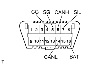
The main body ECU uses ISO 15765-4 for communication protocol. The terminal arrangement of the DLC3 complies with ISO 15031-3 and matches the ISO 15765-4 format.
| Tester Connection | Terminal Description | Condition | Specified condition |
| 7 (SIL) - 5 (SG) | Bus "+" line | During transmission | Pulse generation |
| 4 (CG) - Body ground | Chassis ground | Always | Below 1 Ω |
| 5 (SG) - Body ground | Signal ground | Always | Below 1 Ω |
| 16 (BAT) - Body ground | Battery positive | Always | 11 to 14 V |
| 6 (CANH) - 14 (CANL) | CAN bus line | Engine switch off*
| 54 to 69 Ω |
| 6 (CANH) - 4 (CG) | HIGH-level CAN bus line | Engine switch off*
| 200 Ω or higher |
| 14 (CANL) - 4 (CG) | LOW-level CAN bus line | Engine switch off*
| 200 Ω or higher |
| 6 (CANH) - 16 (BAT) | HIGH-level CAN bus line | Engine switch off*
| 6 kΩ or higher |
| 14 (CANL) - 16 (BAT) | LOW-level CAN bus line | Engine switch off*
| 6 kΩ or higher |
- NOTICE:
- *: Before measuring the resistance, leave the vehicle as is for at least 1 minute and do not operate the engine switch, any other switches or the doors.
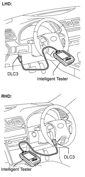 |
Connect the cable of the intelligent tester to the DLC3, turn the engine switch on (IG) and attempt to use the intelligent tester. If the screen displays a communication error message, a problem exists in the vehicle or in the tester.
- If communication is normal when the tool is connected to another vehicle, inspect the DLC3 on the original vehicle.
- If communication is still impossible when the tool is connected to another vehicle, the problem is probably in the tool itself. Consult the Service Department listed in the tool instruction manual.