Home › ENGINE ยท 2AZ-FE › LUBRICATION › OIL PUMP

OIL PUMP > INSPECTION

for Preparation Click here


1. INSPECT OIL JET


    A126890
  1. Check the oil jet for damage or clogging.
    If necessary, repair the cylinder block.


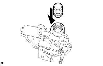
2. INSPECT OIL PUMP RELIEF VALVE


    A114340
  1. Check the relief valve.

    1. Coat the valve with engine oil, and then check that the valve falls smoothly into the valve hole under its own weight.
      If the valve does not fall smoothly, replace the relief valve. If necessary, replace the oil pump assembly.


3. INSPECT OIL PUMP ROTOR


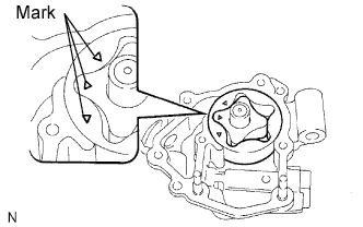
  1. Install the oil pump rotor.


      B011423E04
    1. Coat the drive rotor and driven rotor with engine oil.

    2. Place the drive and driven rotors into the oil pump with the marks facing the pump cover side.
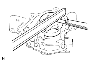


    B011420E02
  1. Check the side clearance.

    1. Using a feeler gauge and precision straightedge, measure the clearance between the rotors and precision straightedge.
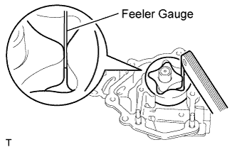
      Standard clearance:
      0.030 to 0.085 mm (0.0012 to 0.0033 in.)

      Maximum clearance:
      0.16 mm (0.0063 in.)

      If the side clearance is greater than the maximum, replace the oil pump assembly.


    A114223E01
  1. Check the tip clearance.

    1. Using a feeler gauge, measure the clearance between the drive and driven rotor tips.
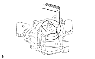
      Standard clearance:
      0.080 to 0.160 mm (0.0031 to 0.0063 in.)

      Maximum clearance:
      0.35 mm (0.0138 in.)

      If the tip clearance is greater than the maximum, replace the oil pump assembly.


    B011422E01
  1. Check the body clearance.

    1. Using a feeler gauge, measure the clearance between the driven rotor and pump body.

      Standard clearance:
      0.100 to 0.170 mm (0.0039 to 0.0067 in.)

      Maximum clearance:
      0.325 mm (0.0128 in.)

      If the body clearance is greater than the maximum, replace the oil pump assembly.


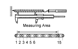
4. INSPECT NO. 2 CHAIN SUB-ASSEMBLY


    A135727E01
  1. Pull the chain with a force of 140 N (14.3 kgf, 31.5 lbf) as shown in the illustration.

  1. Using vernier calipers, measure the length of 15 links.

    Maximum chain elongation:
    102.2 mm (4.024 in.)

    NOTICE:
    Perform the measurement at 3 random places. Use the average of the measurements.

    If the elongation is greater than the maximum, replace the No. 2 chain.


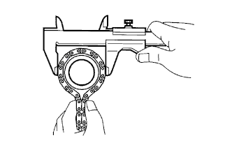
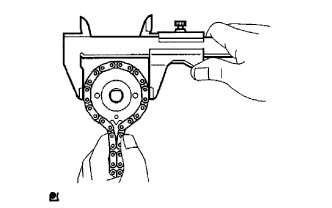
5. INSPECT OIL PUMP DRIVE SPROCKET


    A053035E01
  1. Wrap the chain around the sprocket.

  1. Using vernier calipers, measure the sprocket diameter with the chain wrapped around.

    Minimum gear diameter (with chain):
    48.2 mm (1.898 in.)

    NOTICE:
    The vernier calipers must be in contact with the chain rollers when measuring.

    If the diameter is less than the minimum, replace the chain and sprocket.


6. INSPECT OIL PUMP DRIVEN SPROCKET


    A053036E01
  1. Wrap the chain around the sprocket.

  1. Using vernier calipers, measure the sprocket diameter with the chain wrapped around.

    Minimum gear diameter (with chain):
    48.2 mm (1.898 in.)

    NOTICE:
    The vernier calipers must be in contact with the chain rollers when measuring.

    If the diameter is less than the minimum, replace the chain and sprocket.


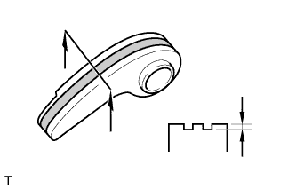
7. INSPECT CHAIN TENSIONER PLATE


    A126893
  1. Using vernier calipers, measure the vibration damper wear.

    Maximum wear:
    0.5 mm (0.020 in.)

    If the wear is greater than the maximum, replace the chain tensioner plate.