 |
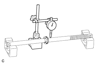
Using a dial indicator, check for runout of the steering rack and teeth wear.
- Maximum runout:
- 0.3 mm (0.0118 in.)
- NOTICE:
- Make sure that the steering rack is placed horizontally.
POWER STEERING LINK > INSPECTION |
| 1. INSPECT POWER STEERING RACK |
|
Using a dial indicator, check for runout of the steering rack and teeth wear.
Check the rack surface for wear and damage.
| 2. INSPECT TIE ROD ASSEMBLY LH |
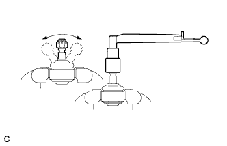 |
Secure the tie rod assembly LH in a vise.
Install the nut to the stud bolt.
Flip the ball joint back and forth 5 times or more.
Using a torque wrench, turn the nut continuously at a rate of 3 to 5 seconds per turn and take the torque reading on the 5th turn.
| 3. INSPECT TIE ROD ASSEMBLY RH |
| 4. INSPECT TOTAL PRELOAD |
Temporarily install the 2 steering rack ends to the power steering rack.
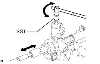 |
Using SST, fully turn the power steering rack right and left 10 times to settle it.
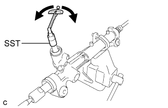 |
Using SST, turn the control valve and measure the preload.
Remove the 2 steering rack ends from the power steering rack.