 |
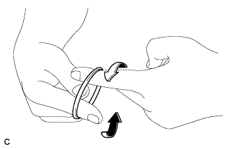
Expand a new power piston oil seal with your fingers.
- NOTICE:
- Be careful not to expand the oil seal excessively.
POWER STEERING LINK > REASSEMBLY |
| 1. INSTALL POWER PISTON OIL SEAL |
Coat a new O-ring with power steering fluid and install it to the steering rack.
|
Expand a new power piston oil seal with your fingers.
Coat the power piston oil seal with power steering fluid.
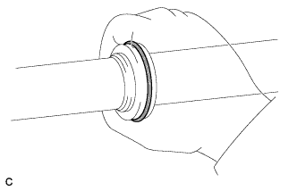 |
Install the power piston oil seal to the steering rack, and adjust it with your fingers.
| 2. INSTALL POWER STEERING CYLINDER TUBE OIL SEAL |
Apply power steering fluid to the lip of a new power steering cylinder tube oil seal.
Install the power steering cylinder tube oil seal to the rack housing at a slant.
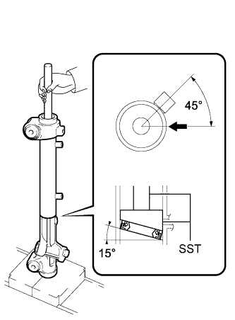 |
Using SST, insert the power steering cylinder tube oil seal by pushing the SST in by hand until the oil seal passes the 2 ports.
Install SST (09631-00200) to SST (09951-07360) upside down.
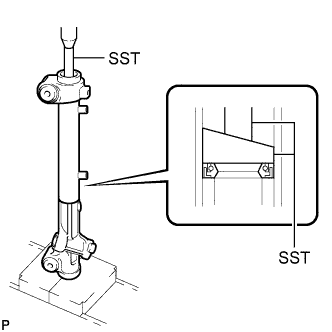 |
Using SST, level the power steering cylinder tube oil seal by pushing the SST in by hand. Using SST and a press, install the oil seal.
| 3. INSTALL POWER STEERING RACK SUB-ASSEMBLY |
Apply molybdenum disulfide lithium base grease to the rack teeth ends.
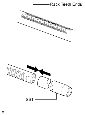 |
Connect SST to the power steering rack sub-assembly.
Coat SST with power steering fluid.
Install the power steering rack sub-assembly to the power steering rack housing.
Remove SST.
| 4. INSTALL POWER STEERING RACK BUSHING |
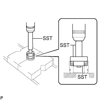 |
Using SST and a press, install the rack bushing oil seal to the power steering rack bushing.
Coat a new O-ring with power steering fluid and install it to the rack bushing.
Coat the rack bushing oil seal lip with power steering fluid.
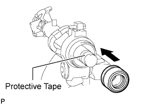 |
Install the power steering rack bushing to the power steering rack housing.
| 5. INSTALL CYLINDER END STOPPER |
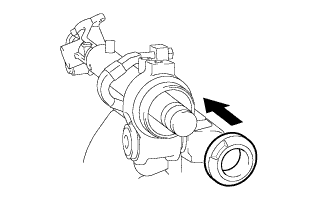 |
Install the cylinder end stopper to the power steering rack housing.
| 6. INSTALL CYLINDER END STOPPER HOLE SNAP RING |
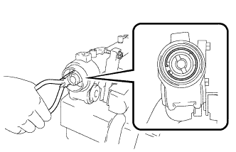 |
Using needle nose pliers, install the cylinder end stopper hole snap ring to the power steering rack housing.
| 7. AIR TIGHTNESS TEST |
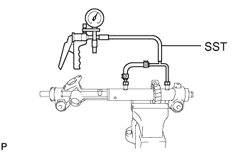 |
Install SST to the power steering rack housing.
Apply a vacuum of 53 kPa (398 mmHg, 15.65 in.Hg) for approximately 30 seconds.
Check that there is no change in the vacuum pressure.
If there is a change in the vacuum pressure, check the installation of the oil seals.
| 8. INSTALL POWER STEERING CONTROL VALVE UPPER OIL SEAL |
Coat a new power steering control valve upper oil seal lip with power steering fluid.
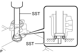 |
Using SST and a press, press in the power steering control valve upper oil seal.
| 9. INSTALL POWER STEERING CONTROL VALVE UPPER BEARING |
Coat the power steering control valve upper bearing with molybdenum disulfide lithium base grease.
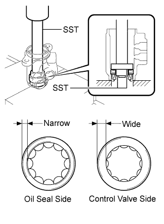 |
Using SST and a press, press in the power steering control valve upper bearing.
| 10. INSTALL POWER STEERING CONTROL VALVE SPACER |
|
Expand 4 new power steering control valve spacers with your fingers.
Coat the 4 power steering control valve spacers with power steering fluid.
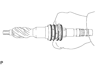 |
Install the 4 power steering control valve spacers to the control valve, and adjust them with your fingers.
| 11. INSTALL POWER STEERING CONTROL VALVE SUB-ASSEMBLY |
Coat the power steering control valve sub-assembly with power steering fluid.
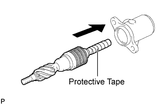 |
Install the power steering control valve sub-assembly into the control valve housing sub-assembly.
| 12. INSTALL POWER STEERING CONTROL VALVE LOWER OIL SEAL |
Coat a new power steering control valve lower oil seal lip with power steering fluid.
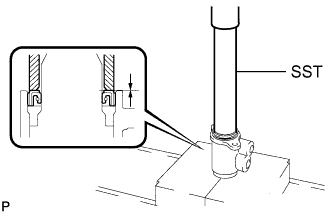 |
Using SST and a press, install the power steering control valve lower oil seal to the control valve assembly.
| 13. INSTALL POWER STEERING CONTROL VALVE ASSEMBLY |
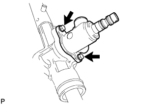 |
Install the power steering control valve assembly and a new gasket to the power steering rack housing with the 2 bolts.
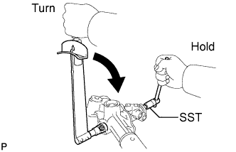 |
Using SST, hold the control valve shaft and install a new nut.
Apply sealant to 2 or 3 threads of the rack housing cap.
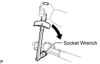 |
Using a socket wrench (27 mm (1.06 in.)), install the rack housing cap.
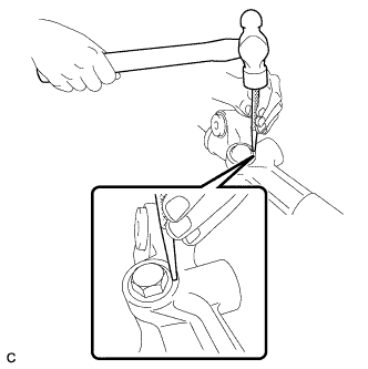 |
Using a punch and a hammer, stake the rack housing cap and the power steering rack housing.
| 14. INSTALL RACK GUIDE |
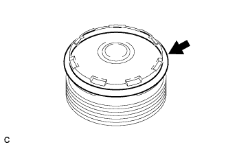 |
Coat a new O-ring with molybdenum disulfide lithium base grease and install it to the rack guide spring cap.
Apply molybdenum disulfide lithium base grease to the rack guide base and rack guide.
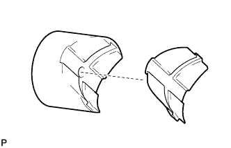 |
Install the rack guide base to the rack guide.
Apply molybdenum disulfide lithium base grease to the compression spring and the contact surface of the rack guide sub-assembly and the power steering rack.
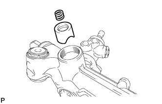 |
Install the compression spring and rack guide sub-assembly to the power steering rack housing.
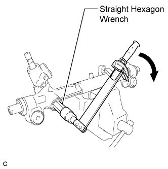 |
Using a straight hexagon wrench (24 mm (0.94 in.)), install the rack guide spring cap to the power steering rack housing.
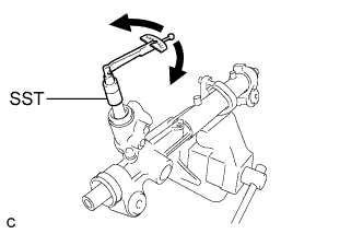 |
Using SST, turn the control valve and measure the turning torque.
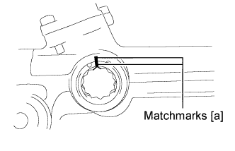 |
Put matchmarks [a] on the power steering rack housing and the rack guide spring cap.
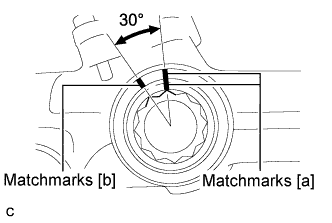 |
Put matchmarks [b] 30° counterclockwise from matchmarks [a] on the power steering rack housing.
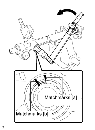 |
Using a straight hexagon wrench (24 mm (0.94 in.)), loosen the rack guide spring cap until matchmarks [b] and matchmarks [a] on the rack guide spring cap are aligned. Measure the rotating torque required when loosening the rack guide spring cap.
If the rotating torque required when loosening is below the specified value, perform the following procedure to achieve the specified value.
|
Using a straight hexagon wrench (24 mm (0.94 in.)), re-tighten the rack guide spring cap.
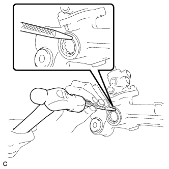 |
Using a punch and hammer, stake the power steering rack housing and rack guide spring cap at 3 equally spaced positions.
|
Using a straight hexagon wrench (24 mm (0.94 in.)), loosen the rack guide spring cap until matchmarks [b] and matchmarks [a] on the rack guide spring cap are aligned. Measure the rotating torque required when loosening the rack guide spring cap.
| 15. INSPECT TOTAL PRELOAD |
Temporarily install the 2 steering rack ends to the power steering rack.
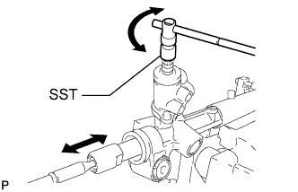 |
Using SST, fully turn the power steering rack right and left 10 times to settle it.
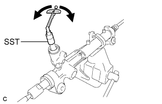 |
Using SST, turn the control valve and measure the preload.
Remove the 2 steering rack ends from the power steering rack.
| 16. INSTALL DUST COVER |
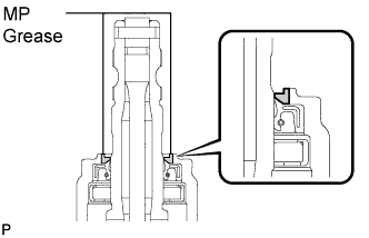 |
Apply MP grease around the control valve shaft as shown in the illustration.
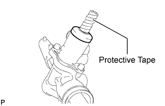 |
Wrap vinyl tape around the spline of the control valve.
Install the dust cover to the control valve assembly.
| 17. INSTALL STEERING RACK END SUB-ASSEMBLY |
Install 2 new claw washers.
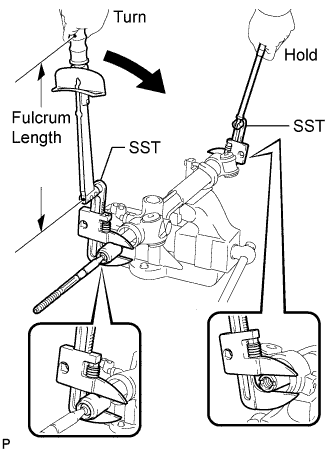 |
Using SST, install the steering rack end sub-assembly (LH side).
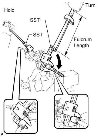 |
Using SST, install the steering rack end sub-assembly (RH side).
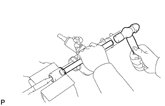 |
Using a brass bar and a hammer, stake the RH and LH claw washers.
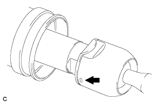 |
Ensure that the holes of the RH and LH rack ends are not clogged with grease.
| 18. INSTALL NO. 2 STEERING RACK BOOT |
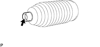 |
Apply silicon grease to the inside of the small opening of the No. 2 steering rack boot.
Install the No. 2 steering rack boot to the groove on the rack housing.
| 19. INSTALL NO. 1 STEERING RACK BOOT |
| 20. INSTALL NO. 2 STEERING RACK BOOT CLAMP |
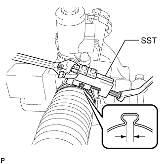 |
Using SST, tighten the RH and LH No. 2 steering rack boot clamps as shown in the illustration.
| 21. INSTALL STEERING RACK BOOT CLIP |
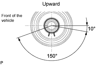 |
Using pliers, install the RH and LH steering rack boot clips.
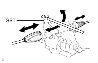 |
Using SST, turn the pinion and check that the rack boots expand and contract smoothly.
| 22. INSTALL TIE ROD ASSEMBLY LH |
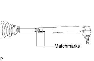 |
Install the lock nut and the tie rod assembly LH to the steering rack end sub-assembly until the matchmarks are aligned.
| 23. INSTALL TIE ROD ASSEMBLY RH |
| 24. INSTALL STEERING RIGHT TURN PRESSURE TUBE |
Coat 2 new O-rings with power steering fluid and install them to the steering right turn pressure tube.
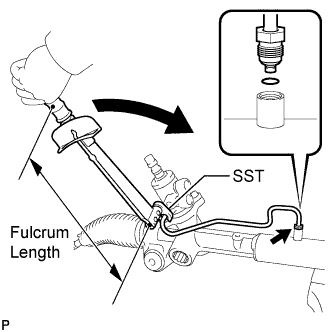 |
Using SST, install the right turn pressure tube to the power steering link assembly.
| 25. INSTALL STEERING LEFT TURN PRESSURE TUBE |
Coat 2 new O-rings with power steering fluid and install them to the steering left turn pressure tube.
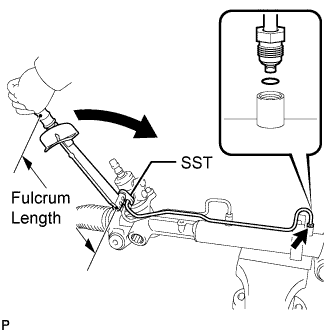 |
Using SST, install the left turn pressure tube to the power steering link assembly.