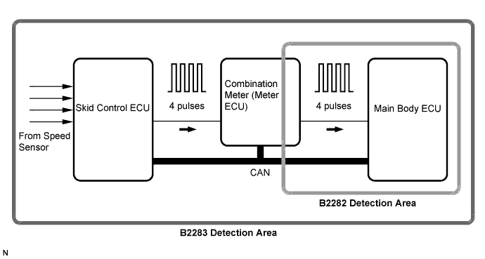
DTC B2283 Vehicle Speed Sensor Malfunction |
| DTC No. | DTC Detection Condition | Trouble Area |
| B2283 | When both conditions below are met:
|
|
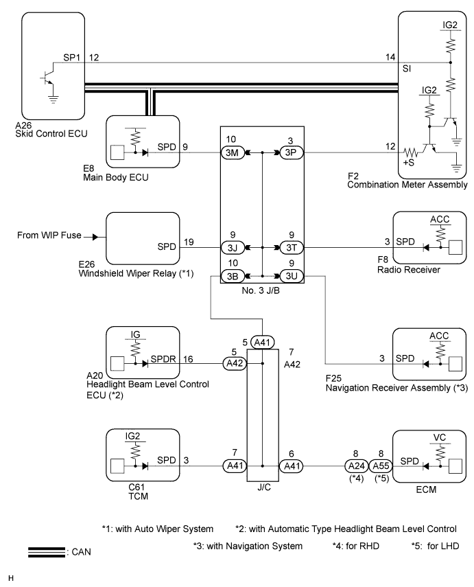
| 1.CHECK DTC OUTPUT (ENTRY AND START SYSTEM) |
Clear the DTCs (Click here).
After all DTCs are cleared, check if the trouble occurs again 320 seconds after the engine switch is turned on (IG).
Check for DTC B2282 and DTC B2283.
| Display (DTC output) | Proceed to |
| "DTC B2283" only | A |
| "DTC B2283" and "DTC B2282" | B |
| No DTC | C |
|
| ||||
|
| ||||
| A | |
 |
| 2.CHECK OPERATION OF SPEEDOMETER |
Drive the vehicle and check if the function of the speedometer in the combination meter is normal.
|
| ||||
| OK | |
|
| 3.CHECK DTC OUTPUT (BRAKE CONTROL) |
Delete the DTCs (Click here).
Check for DTCs (for w/o VSC: Click here) (for w/ VSC: Click here).
|
| ||||
| OK | ||
 | ||
| ||
| 4.CHECK HARNESS AND CONNECTOR (SKID CONTROL ECU - COMBINATION METER) |
Disconnect the F2 meter connector.
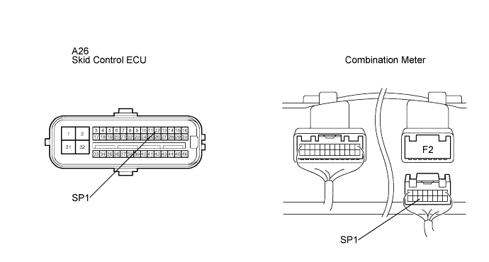
Disconnect the skid control ECU connector.
Measure the resistance according to the value(s) in the table below.
| Tester Connection) | Condition | Specified Condition |
| A26-12 (SP1) - F2-14 (SI) | Always | Below 1 Ω |
| A26-12 (SP1) or F2-14 (SI) - Body ground | Always | 10 kΩ or higher |
|
| ||||
| OK | |
|
| 5.INSPECT COMBINATION METER (SPEED SIGNAL) |
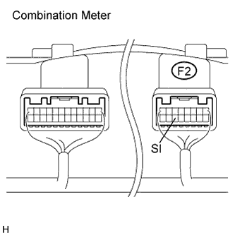 |
Check the input signal waveform.
Reconnect the connectors.
Remove the combination meter assembly with the connector(s) still connected.
Connect an oscilloscope to terminal F2-14 (SI) and body ground.
Turn the engine switch on (IG).
Turn the wheel slowly.
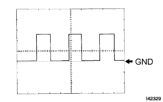 |
Check the signal waveform according to the condition(s) in the table below.
| Item | Condition |
| Tool setting | 5 V/DIV., 10 ms./DIV. |
| Vehicle condition | Driving at approx. 20 km/h (12 mph) |
|
| ||||
| OK | ||
| ||
| ||

