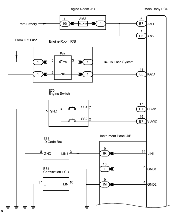
ENTRY AND START SYSTEM > Power Source Mode does not Change to ON (IG and ACC) |
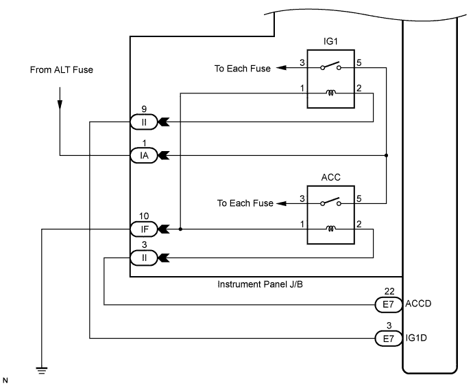
| 1.CHECK ENTRY FUNCTION DETECTION AREA |
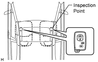 |
Inspect entry detection area.
When the electrical key is in either of the 2 inspection points in the illustration, the shift lever is in the P position and the brake pedal is depressed, check that the engine switch indicator illuminates in green.
|
| ||||
| OK | |
 |
| 2.INSPECT FUSE (AM2) |
Remove the AM2 fuse from the engine room J/B.
Measure the resistance according to the value(s) in the table below.
| Tester Connection | Condition | Specified Condition |
| AM2 fuse | Always | Below 1 Ω |
|
| ||||
| OK | |
|
| 3.CHECK CONNECTORS |
Check that the connectors are securely connected and the terminals are not deformed or loose.
|
| ||||
| OK | |
|
| 4.CHECK HARNESS AND CONNECTOR (MAIN BODY ECU - BATTERY) |
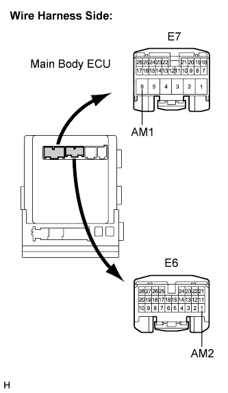 |
Disconnect the E6 and E7 ECU connectors.
Measure the voltage according to the value(s) in the table below.
| Tester Connection | Condition | Specified Condition |
| E7-6 (AM1) - Body ground | Always | 11 to 14 V |
| E6-1 (AM2) - Body ground | Always | 11 to 14 V |
|
| ||||
| OK | |
|
| 5.CHECK HARNESS AND CONNECTOR (MAIN BODY ECU - BODY GROUND) |
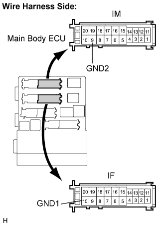 |
Disconnect the IF and IM ECU connectors.
Measure the resistance according to the value(s) in the table below.
| Tester Connection | Condition | Specified Condition |
| IF-10 (GND1) - Body ground | Always | Below 1 Ω |
| IM-9 (GND2) - Body ground | Always | Below 1 Ω |
|
| ||||
| OK | |
|
| 6.CHECK FOR DTCS |
Delete the DTCs (Click here).
Check for DTCs again.
|
| ||||
| OK | |
|
| 7.READ VALUE USING INTELLIGENT TESTER |
Connect the intelligent tester to the DLC3.
Turn the engine switch on (IG).
Turn the intelligent tester on.
Enter the following menus: Body / Body / Data List.
Read the Data List according to the display on the intelligent tester.
| Tester Display | Measurement Item/Range | Normal Condition | Diagnostic Note |
| St SW 1 | Start Switch 1/ON or OFF | ON: Engine switch on (IG) OFF: Engine switch off | - |
| St SW 2 | Start Switch 2/ON or OFF | ON: Engine switch on (IG) OFF: Engine switch off | - |
|
| ||||
| NG | |
|
| 8.INSPECT ENGINE SWITCH |
Remove the engine switch (Click here).
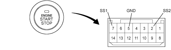
Measure the resistance of the switch.
| Tester Connection | Switch Condition | Specified Condition |
| 7 (SS1) - 5 (GND) | Pushed | Below 1 Ω |
| 2 (SS2) - 5 (GND) | Pushed | Below 1 Ω |
| 7 (SS1) - 5 (GND) | Not pushed | 10 kΩ or higher |
| 2 (SS2) - 5 (GND) | Not pushed | 10 kΩ or higher |
|
| ||||
| OK | |
|
| 9.CHECK HARNESS AND CONNECTOR (MAIN BODY ECU AND BODY GROUND - ENGINE SWITCH) |
Disconnect the E7 ECU connector.
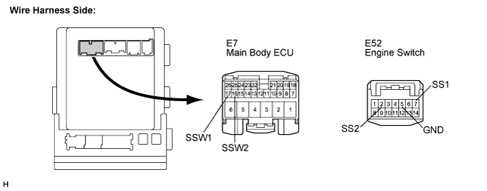
Measure the resistance according to the value(s) in the table below.
| Tester Connection | Condition | Specified Condition |
| E52-7 (SS1) - E7-17 (SSW1) | Always | Below 1 Ω |
| E52-2 (SS2) - E7-16 (SSW2) | Always | Below 1 Ω |
| E52-5 (GND) - Body ground | Always | Below 1 Ω |
| E52-7 (SS1) or E7-17 (SSW1) - Body ground | Always | 10 kΩ or higher |
| E52-2 (SS2) or E7-16 (SSW2) - Body ground | Always | 10 kΩ or higher |
|
| ||||
| OK | ||
 | ||
| ||
