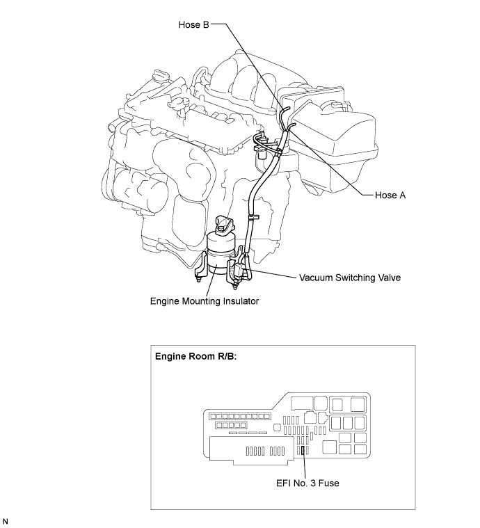
SFI SYSTEM > Active Control Engine Mount System |
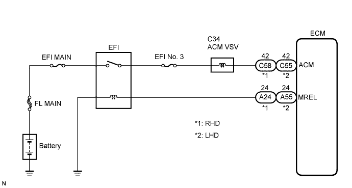
| 1.CHECK VACUUM HOSES |
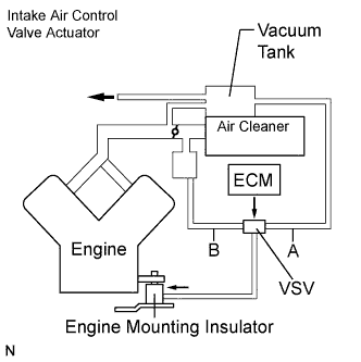 |
If the hose is damaged, replace the vacuum hose assembly.
Check the air and vacuum hoses for looseness, disconnection and blockage.
|
| ||||
| OK | |
 |
| 2.CHECK VACUUM |
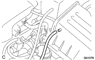 |
Start the engine.
Disconnect the vacuum hose from the air cleaner cap.
Check that the disconnected port located on the vacuum tank applies suction to your finger.
Reconnect the vacuum hose.
|
| ||||
| OK | |
|
| 3.INSPECT DUTY VACUUM SWITCHING VALVE (OPERATION) |
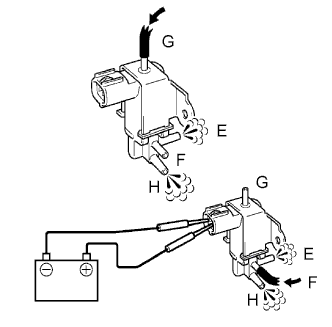 |
Remove the VSV for ACM.
Check operation of the VSV for ACM when positive battery voltage is applied to the terminals of the VSV for ACM connector.
Reinstall the VSV for ACM.
|
| ||||
| OK | |
|
| 4.INSPECT DUTY VACUUM SWITCHING VALVE (RESISTANCE) |
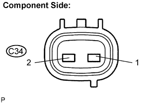 |
Disconnect the C34 VSV for ACM connector.
Measure the resistance between terminals 1 and 2.
Reconnect the VSV for ACM connector.
|
| ||||
| OK | |
|
| 5.INSPECT FRONT ENGINE MOUNTING INSULATOR ASSEMBLY |
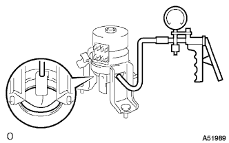 |
Disconnect the vacuum hose from the front engine mounting insulator.
Using a vacuum pump, apply vacuum of 80 kPa (600 mmHg, 25 in.Hg) and wait for 1 minute.
Check that there is no change in the needle movement of the vacuum pump gauge.
Check that there is no fluid leakage caused by a break in the diaphragm.
Reconnect the vacuum hose.
|
| ||||
| OK | |
|
| 6.CHECK HARNESS AND CONNECTOR (VSV FOR ACM - ECM) |
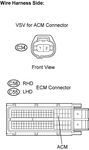 |
Check the wire harness between the VSV for ACM connector and the ECM connector.
Disconnect the C34 VSV for ACM connector.
Disconnect the C58 (RHD) or C55 (LHD) ECM connector.
Measure the resistance between the wire harness side connectors.
| Tester Connection | Specified Condition |
| VSV for ACM (C34-2) - ACM (C58-42) | Below 1 Ω |
| Tester Connection | Specified Condition |
| VSV for ACM (C34-2) - ACM (C55-42) | Below 1 Ω |
| Tester Connection | Specified Condition |
| VSV for ACM (C34-2) or ACM (C58-42) - Body ground | 10 kΩ or higher |
| Tester Connection | Specified Condition |
| VSV for ACM (C34-2) or ACM (C55-42) - Body ground | 10 kΩ or higher |
Reconnect the ECM connector.
Reconnect the VSV connector.
|
| ||||
| OK | |
|
| 7.INSPECT DUTY VACUUM SWITCHING VALVE (VOLTAGE) |
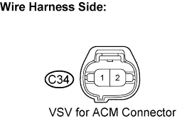 |
Disconnect the C34 VSV connector.
Turn the ignition switch to the ON position.
Measure the voltage between the terminals.
| Tester Connection | Specified Condition |
| C34-1 - Body ground | 9 to 14 V |
|
| ||||
| OK | ||
 | ||
| ||
| 8.CHECK HARNESS AND CONNECTOR (VSV FOR ACM - ENGINE JUNCTION BLOCK (EFI RELAY)) |
Check the wire harness between the VSV for ACM and the EFI relay.
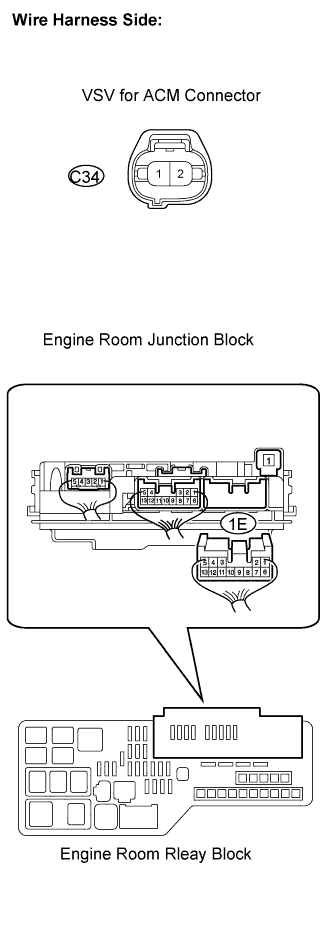 |
Disconnect the C34 VSV connector.
Remove the engine room junction block.
Measure the resistance between the wire harness side connectors.
| Tester Connection | Specified Condition |
| VSV for ACM (C34-1) - 1E-6 (Engine room relay block) | Below 1 Ω |
| Tester Connection | Specified Condition |
| VSV for ACM (C34-1) or 1E-6 (Engine room relay block) - Body ground | 10 kΩ or higher |
Reconnect the VSV for ACM connector.
Reinstall the engine room junction block.
|
| ||||
| OK | |
|
| 9.INSPECT ENGINE ROOM JUNCTION BLOCK (EFI RELAY) |
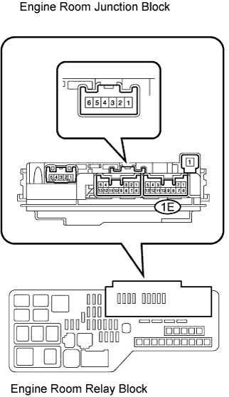 |
Remove the engine room junction block.
Measure the EFI relay resistance.
| Tester Connection | Specified Condition |
| 1E-12 - 1E-6 | 10 kΩ or higher |
| 1E-12 - 1E-6 | Below 1 Ω (Apply battery voltage between terminals 1E-9 and 1E-10) |
Reinstall the engine room junction block.
|
| ||||
| OK | ||
| ||
| ||

