 |
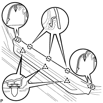
Disengage the 7 claws and 3 clips, and remove the front door scuff plate LH.
COMBINATION METER > REMOVAL |
| 1. DISCONNECT CABLE FROM NEGATIVE BATTERY TERMINAL |
| 2. REMOVE FRONT DOOR SCUFF PLATE LH |
|
Disengage the 7 claws and 3 clips, and remove the front door scuff plate LH.
| 3. REMOVE COWL SIDE TRIM SUB-ASSEMBLY LH |
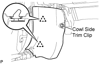 |
Remove the cowl side trim clip.
Disengage the 2 clips and remove the cowl side trim sub-assembly LH.
| 4. REMOVE LOWER INSTRUMENT PANEL FINISH PANEL LH |
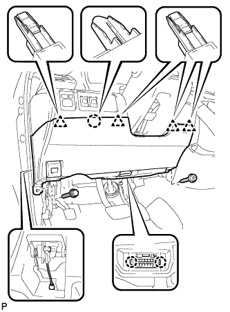 |
Remove the screw and the bolt.
Disconnect the hood lock control cable assembly.
Disengage the claw and the 4 clips.
Disengage the 2 claws and disconnect the connector.
Remove the air hose, disconnect the connector, and then remove the lower instrument panel finish panel LH.
| 5. REMOVE STEERING COLUMN COVER |
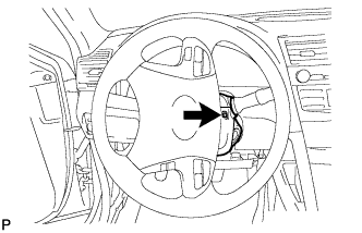 |
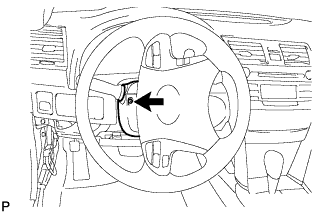
Turn the steering wheel assembly to the right and remove the screw as shown in the illustration.
 |
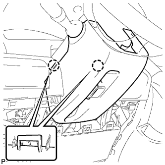
Turn the steering wheel assembly to the left and remove the screw as shown in the illustration.
 |
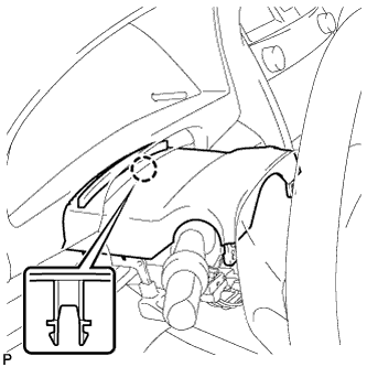
Disengage the 2 claws and remove the steering column cover lower.
 |
Disengage the claw and remove the steering column cover upper.
| 6. REMOVE NO. 1 INSTRUMENT PANEL SUB-ASSEMBLY |
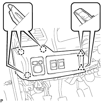 |
Disengage the 3 claws and the 2 clips.
Disconnect each connector and remove the instrument panel sub-assembly.
| 7. REMOVE LOWER INSTRUMENT PANEL FINISH PANEL |
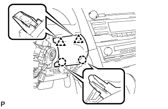 |
Disengage the 2 claws and 2 clips, and then remove the lower instrument panel finish panel.
| 8. REMOVE INSTRUMENT CLUSTER FINISH PANEL NO.1 |
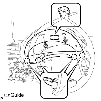 |
Remove the 2 clips.
Disengage the guide and 4 claws, and then remove the instrument cluster finish panel.
| 9. REMOVE COMBINATION METER ASSEMBLY |
Using the tilt and telescopic functions, fully lower and extend the steering wheel.
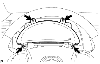 |
Remove the 4 screws.
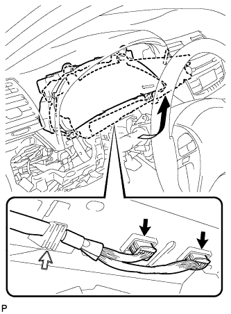 |
Disconnect the 2 connectors.
Disengage the wire harness from the combination meter assembly.
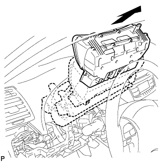 |
Remove the combination meter assembly as shown in the illustration.