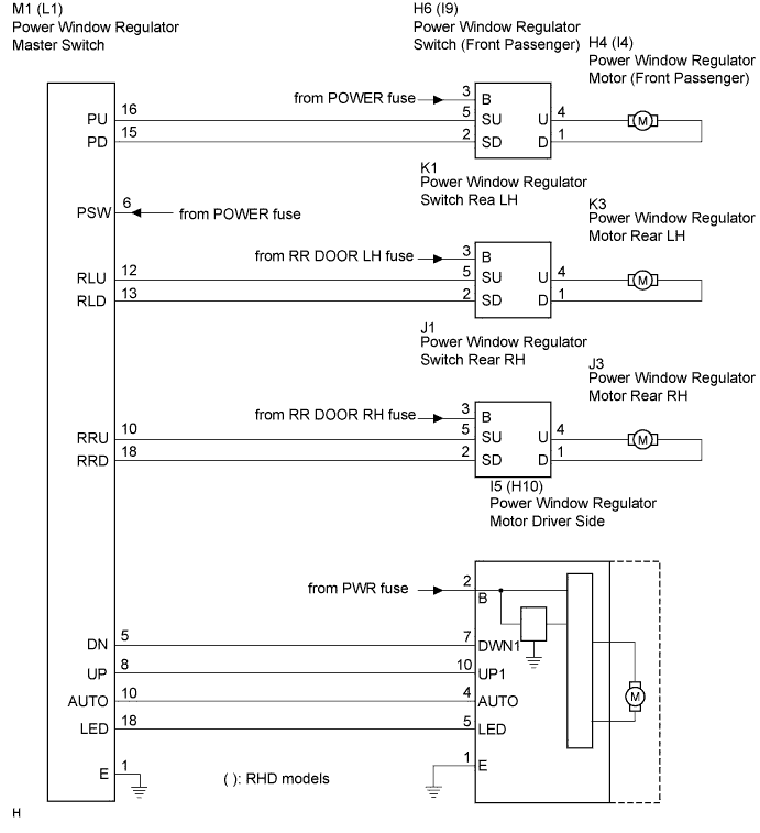
POWER WINDOW CONTROL SYSTEM (for Models with Jam Protection Function on Driver Door Window Only) > Power Window Master Switch Circuit |
| 1.CHECK DTC OUTPUT |
Turn the ignition switch off.
Wait for at least 10 seconds, and then turn the ignition switch ON.
Check whether the DTC output recurs.
| Display (DTC output) | Proceed to |
| No output | A |
| Output DTCs | B |
|
| ||||
| A | |
 |
| 2.INSPECT POWER WINDOW REGULATOR MASTER SWITCH ASSEMBLY |
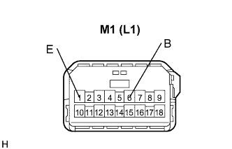 |
Disconnect the M1 (L1) connector.
Measure the voltage and resistance according to the value(s) in the table below.
( ): RHD models
| Tester Connection | Condition | Specified Condition |
| 6 (B) - Body ground | Ignition switch ON | 10 to 14 V |
| Tester Connection | Condition | Specified Condition |
| 1 (E) - Body ground | Always | Below 1 Ω |
|
| ||||
| OK | |
|
| 3.INSPECT POWER WINDOW REGULATOR MASTER SWITCH ASSEMBLY |
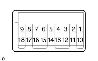 |
Measure the resistance according to the value(s) in the table below.
| Tester Connection | Condition | Specified Condition |
| 8 (UP) - 1 (E) - 4 (AUTO) | Auto UP | Below 1 Ω |
| 5 (DN) - 6 (B) | Below 1 Ω | |
| 8 (UP) - 1 (E) | Manual UP | Below 1 Ω |
| 5 (DN) - 6 (B) | Below 1 Ω | |
| 8 (UP) - 5 (DN) - 6 (B) | OFF | Below 1 Ω |
| 5 (DN) - 1 (E) | Manual DOWN | Below 1 Ω |
| 8 (UP) - 6 (B) | Below 1 Ω | |
| 4 (AUTO) - 5 (DN) - 1 (E) | Auto DOWN | Below 1 Ω |
| 8 (UP) - 6 (B) | Below 1 Ω | |
| 1 (E) - 10 (RRU) | Lock/Unlock switch | UNLOCK (Below 1 Ω) →LOCK (10 kΩ or higher) |
| 1 (E) - 12 (RLU) | ||
| 1 (E) - 13 (RLD) | ||
| 1 (E) - 15 (PD) | ||
| 1 (E) - 16 (PU) | ||
| 1 (E) - 18 (RRD) |
|
| ||||
| OK | |
|
| 4.CHECK WIRE HARNESS (MASTER SWITCH - FRONT PASSENGER, REAR LH/RH SWITCH) |
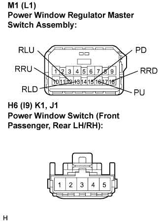 |
Disconnect the M1 (L1), H6 (I9), K1 and J1 connectors.
Measure the resistance according to the value(s) in the table below.
( ): RHD models
| Tester Connection | Condition | Specified Condition |
| M1-16 (PU) - H6-5 (SU) | Always | Below 1 Ω |
| M1-15 (PD) - H6-2 (SD) | Always | Below 1 Ω |
| M1-16 (PU) - Body ground | Always | 10 kΩ or higher |
| M1-15 (PD) - Body ground | Always | 10 kΩ or higher |
| Tester Connection | Condition | Specified Condition |
| M1-12 (RLU) - K1-5 (SU) | Always | Below 1 Ω |
| M1-13 (RLD) - K1-2 (SD) | Always | Below 1 Ω |
| M1-12 (RLU) - Body ground | Always | 10 kΩ or higher |
| M1-13 (RLD) - Body ground | Always | 10 kΩ or higher |
| Tester Connection | Condition | Specified Condition |
| M1-10 (RRU) - J1-5 (SU) | Always | Below 1 Ω |
| M1-18 (RRD) - J1-2 (SD) | Always | Below 1 Ω |
| M1-10 (RRU) - Body ground | Always | 10 kΩ or higher |
| M1-18 (RRD) - Body ground | Always | 10 kΩ or higher |
| Tester Connection | Condition | Specified Condition |
| L1-16 (PU) - I9-5 (SU) | Always | Below 1 Ω |
| L1-15 (PD) - I9-2 (SD) | Always | Below 1 Ω |
| L1-16 (PU) - Body ground | Always | 10 kΩ or higher |
| L1-15 (PD) - Body ground | Always | 10 kΩ or higher |
| Tester Connection | Condition | Specified Condition |
| L1-12 (RLU) - K1-5 (SU) | Always | Below 1 Ω |
| L1-13 (RLD) - K1-2 (SD) | Always | Below 1 Ω |
| L1-12 (RLU) - Body ground | Always | 10 kΩ or higher |
| L1-13 (RLD) - Body ground | Always | 10 kΩ or higher |
| Tester Connection | Condition | Specified Condition |
| L1-10 (RRU) - J1-5 (SU) | Always | Below 1 Ω |
| L1-18 (RRD) - J1-2 (SD) | Always | Below 1 Ω |
| L1-10 (RRU) - Body ground | Always | 10 kΩ or higher |
| L1-18 (RRD) - Body ground | Always | 10 kΩ or higher |
|
| ||||
| OK | ||
 | ||
| ||
