 |
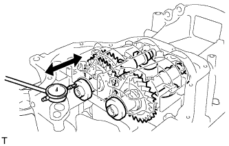
Using a dial indicator, measure the thrust clearance while moving the balanceshaft back and forth.
- Standard thrust clearance:
- 0.05 to 0.09 mm (0.0020 to 0.0035 in.)
- Maximum thrust clearance:
- 0.09 mm (0.0035 in.)
ENGINE UNIT > INSPECTION |
| 1. INSPECT BALANCESHAFT THRUST CLEARANCE |
Install the balanceshafts (Click here).
|
Using a dial indicator, measure the thrust clearance while moving the balanceshaft back and forth.
| 2. INSPECT BALANCESHAFT OIL CLEARANCE |
Clean each bearing and journal.
Check each bearing and journal for pitting and scratches.
If a bearing or journal is damaged, replace the bearings. If necessary, replace the balanceshaft.
Place the No. 1 and No. 2 balanceshafts onto the crankcase.
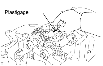 |
Lay a strip of Plastigage across each journal.
Install the balanceshaft housing (Click here).
Remove the balanceshafts (Click here).
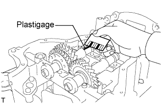 |
Measure the Plastigage at its widest point.
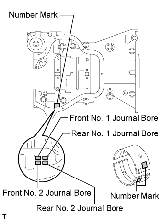 |
If replacing a bearing, select a new one with the same number.
| Item | Specified Condition |
| Mark 1 | 26.000 to 26.006 mm (1.0236 to 1.0239 in.) |
| Mark 2 | 26.007 to 26.012 mm (1.0239 to 1.0241 in.) |
| Mark 3 | 26.013 to 26.018 mm (1.0241 to 1.0243 in.) |
| Item | Specified Condition |
| Mark 1 | 1.486 to 1.489 mm (0.05850 to 0.05862 in.) |
| Mark 2 | 1.490 to 1.492 mm (0.05866 to 0.05874 in.) |
| Mark 3 | 1.493 to 1.495 mm (0.0588 to 0.0589 in.) |
| Item | Journal diameter |
| Mark 1 | 22.985 to 23.000 mm (0.9049 to 0.9055 in.) |
| Mark 2 | 22.985 to 23.000 mm (0.9049 to 0.9055 in.) |
| Mark 3 | 22.985 to 23.000 mm (0.9049 to 0.9055 in.) |
Inspect the balanceshaft housing bolts.
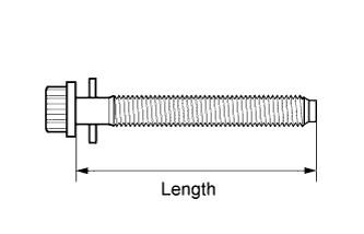 |
Using vernier calipers, measure the length of the bolts from the seat to the end.
| 3. INSPECT CHAIN SUB-ASSEMBLY |
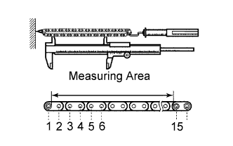 |
Pull the chain with a force of 140 N (14.3 kgf, 31.5 lbf) as shown in the illustration.
Using vernier calipers, measure the length of 15 links.
| 4. INSPECT NO. 2 CHAIN SUB-ASSEMBLY |
|
Pull the chain with a force of 140 N (14.3 kgf, 31.5 lbf) as shown in the illustration.
Using vernier calipers, measure the length of 15 links.
| 5. INSPECT OIL PUMP DRIVE GEAR |
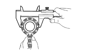 |
Wrap the chain around the sprocket.
Using vernier calipers, measure the sprocket diameter with the chain wrapped around.
| 6. INSPECT OIL PUMP DRIVE SHAFT GEAR |
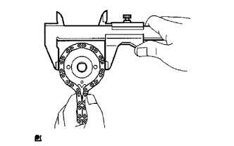 |
Wrap the chain around the sprocket.
Using vernier calipers, measure the sprocket diameter with the chain wrapped around.
| 7. INSPECT CAMSHAFT TIMING GEAR ASSEMBLY |
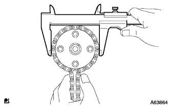 |
Wrap the chain around the sprocket.
Using vernier calipers, measure the sprocket diameter with the chain wrapped around.
| 8. INSPECT CAMSHAFT TIMING SPROCKET |
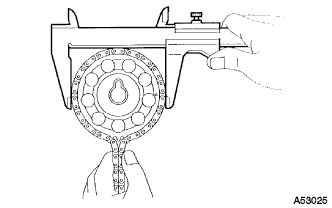 |
Wrap the chain around the sprocket.
Using vernier calipers, measure the sprocket diameter with the chain wrapped around.
| 9. INSPECT CRANKSHAFT TIMING GEAR |
|
Wrap the chain around the timing sprocket.
Using vernier calipers, measure the timing gear diameter with the chain wrapped around.
| 10. INSPECT CHAIN TENSIONER SLIPPER |
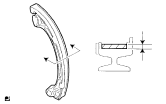 |
Using vernier calipers, measure the tensioner slipper wear.
| 11. INSPECT NO. 1 CHAIN VIBRATION DAMPER |
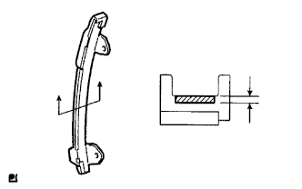 |
Using vernier calipers, measure the vibration damper wear.
| 12. INSPECT CHAIN TENSIONER PLATE |
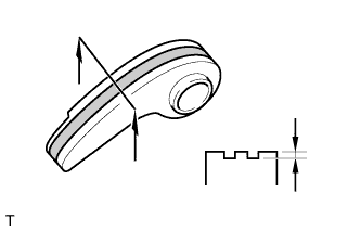 |
Using vernier calipers, measure the vibration damper wear.
| 13. INSPECT NO. 1 CHAIN TENSIONER |
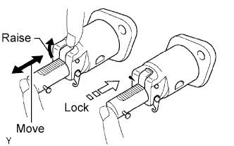 |
Check that the plunger moves smoothly when the ratchet pawl is raised with your finger.
Release the ratchet pawl, then check that the plunger is locked in place by the ratchet pawl and does not move when pushed with your finger.
| 14. INSPECT CONNECTING ROD THRUST CLEARANCE |
Install the connecting rod cap (Click here).
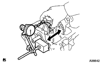 |
Using a dial indicator, measure the thrust clearance while moving the connecting rod back and forth.
| 15. INSPECT CONNECTING ROD OIL CLEARANCE |
Clean the crank pin and bearing.
Check the crank pin and bearing for pitting and scratches.
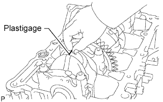 |
Lay a strip of Plastigage on the crank pin.
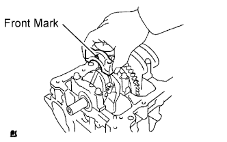 |
Check that the front mark of the connecting rod cap is facing forward.
Install the connecting rod cap (Click here).
Remove the 2 bolts and connecting rod cap (Click here).
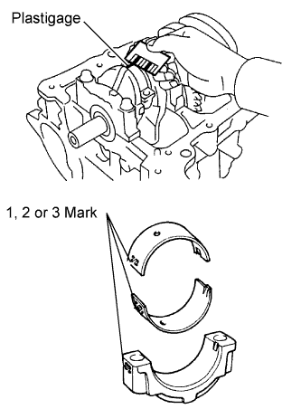 |
Measure the Plastigage at its widest point.
| Mark | Specified Condition |
| Mark 1 | 51.000 to 51.007 mm (2.0079 to 2.0082 in.) |
| Mark 2 | 51.008 to 51.013 mm (2.0082 to 2.0084 in.) |
| Mark 3 | 51.014 to 51.020 mm (2.0084 to 2.0087 in.) |
| Mark | Specified Condition |
| Mark 1 | 1.485 to 1.488 mm (0.0585 to 0.0586 in.) |
| Mark 2 | 1.489 to 1.491 mm (0.0586 to 0.0587 in.) |
| Mark 3 | 1.492 to 1.494 mm (0.0587 to 0.0588 in.) |
| Mark | Specified Condition |
| Mark 1 | 47.990 to 48.000 (1.8894 to 1.8898 in.) |
| Mark 2 | 47.990 to 48.000 (1.8894 to 1.8898 in.) |
| Mark 3 | 47.990 to 48.000 (1.8894 to 1.8898 in.) |
| 16. INSPECT CYLINDER BLOCK FOR WARPAGE |
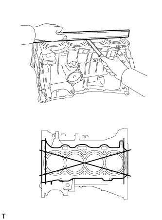 |
Using a precision straightedge and feeler gauge, measure the warpage of the surface that is in contact with the cylinder head gasket.
| 17. INSPECT CYLINDER BORE |
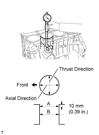 |
Using a cylinder gauge, measure the cylinder bore diameter at positions A and B in the thrust and axial directions.
| 18. INSPECT PISTON |
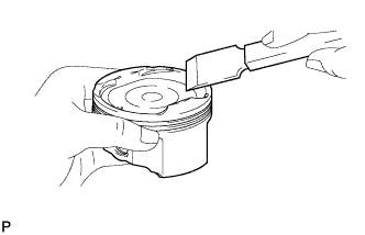 |
Using a gasket scraper, remove the carbon from the piston top.
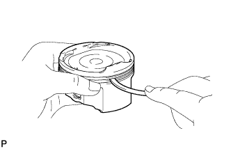 |
Using a groove cleaning tool or a broken ring, clean the piston ring grooves.
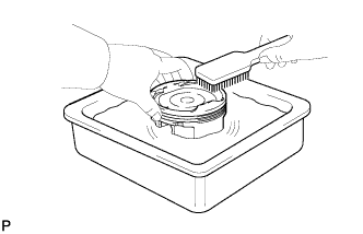 |
Using a brush and solvent, thoroughly clean the piston.
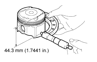 |
Using a micrometer, measure the piston diameter at right angles to the piston pin hole, and at the piston 44.3 mm (1.7441 in.) from the piston head.
| 19. INSPECT PISTON OIL CLEARANCE |
Subtract the piston diameter measurement from the cylinder bore diameter measurement.
| 20. INSPECT RING GROOVE CLEARANCE |
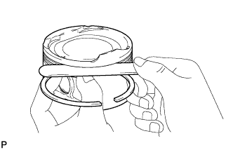 |
Using a feeler gauge, measure the clearance between a new piston ring and wall of the ring groove.
| Item | Specified Condition |
| No. 1 Ring | 0.020 to 0.070 mm (0.0008 to 0.0028 in.) |
| No. 2 Ring | 0.020 to 0.060 mm (0.0008 to 0.0024 in.) |
| Oil Ring | 0.020 to 0.070 mm (0.0008 to 0.0028 in.) |
| 21. INSPECT PISTON RING END GAP |
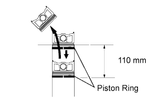 |
Using a piston, push the piston ring a little beyond the bottom of the ring travel, 110 mm (4.33 in.) from the top of the cylinder block.
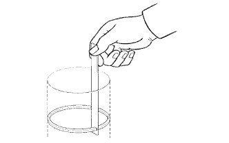 |
Using a feeler gauge, measure the end gap.
| Item | Specified Condition |
| No. 1 Ring | 0.24 to 0.31 mm (0.0094 to 0.0122 in.) |
| No. 2 Ring | 0.33 to 0.43 mm (0.0130 to 0.0169 in.) |
| Oil Ring | 0.10 to 0.30 mm (0.0040 to 0.0119 in.) |
| Item | Specified Condition |
| No. 1 Ring | 0.89 mm (0.0350 in.) |
| No. 2 Ring | 1.37 mm (0.0539 in.) |
| Oil Ring | 0.73 mm (0.0287 in.) |
| 22. INSPECT PISTON PIN OIL CLEARANCE |
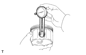 |
Using a caliper gauge, measure the piston pin bore diameter.
| Item | Specified Condition |
| A | 22.001 to 22.004 mm (0.8662 to 0.8663 in.) |
| B | 22.005 to 22.007 mm (0.8663 to 0.8664 in.) |
| C | 22.008 to 22.010 mm (0.8665 to 0.8665 in.) |
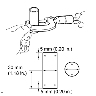 |
Using a micrometer, measure the piston pin diameter.
| Item | Specified Condition |
| A | 21.997 to 22.000 mm (0.8660 to 0.8661 in.) |
| B | 22.001 to 22.003 mm (0.8662 to 0.8663 in.) |
| C | 22.004 to 22.006 mm (0.8663 to 0.8664 in.) |
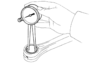 |
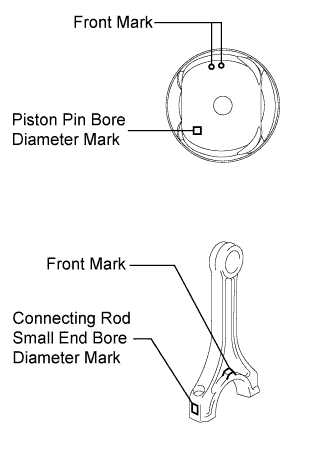
Using a caliper gauge, measure the connecting rod small end bore diameter.
| Item | Specified Condition |
| A | 22.005 to 22.008 mm (0.8663 to 0.8665 in.) |
| B | 22.009 to 22.011 mm (0.8665 to 0.8666 in.) |
| C | 22.012 to 22.014 mm (0.8666 to 0.8667 in.) |
 |
Subtract the piston pin diameter measurement from the piston pin bore diameter measurement.
Subtract the piston pin diameter measurement from the connecting rod small end bore diameter measurement.
| 23. INSPECT CONNECTING ROD BOLT |
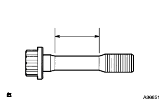 |
Using vernier calipers, measure the tension portion diameter of the bolt.
| 24. INSPECT CONNECTING ROD SUB-ASSEMBLY |
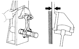 |
Using a connecting rod aligner and feeler gauge, check the connecting rod alignment.
Check for misalignment.
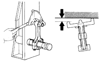 |
Check for twist.
| 25. INSPECT CRANKSHAFT |
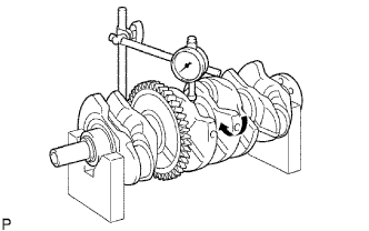 |
Using a dial indicator and V-blocks, measure the circle runout as shown in the illustration.
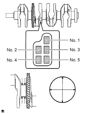 |
Using a micrometer, measure the diameter of each main journal.
Check each main journal for taper and distortion as shown in the illustration.
| Mark | Specified Condition |
| 0 | 54.999 to 55.000 mm (2.1653 to 2.1654 in.) |
| 1 | 54.997 to 54.998 mm (2.1652 to 2.1653 in.) |
| 2 | 54.995 to 54.996 mm (2.1652 to 2.1652 in.) |
| 3 | 54.993 to 54.994 mm (2.1651 to 2.1651 in.) |
| 4 | 54.991 to 54.992 mm (2.1650 to 2.1650 in.) |
| 5 | 54.988 to 54.990 mm (2.1649 to 2.1650 in.) |
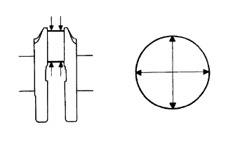 |
Using a micrometer, measure the diameter of each crank pin.
Inspect each crank pin for taper and distortion as shown in the illustration.
| 26. INSPECT CRANKSHAFT THRUST CLEARANCE |
Install the main bearing cap (Click here).
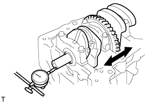 |
Using a dial indicator, measure the thrust clearance while prying the crankshaft back and forth with a screwdriver.
| 27. INSPECT CRANKSHAFT OIL CLEARANCE |
Check the crank journal and bearing for pitting and scratches.
Install the crankshaft bearing (Click here).
Place the crankshaft on the cylinder block.
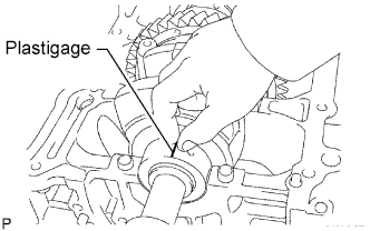 |
Lay a strip of Plastigage across each journal.
Examine the front marks and numbers and install the bearing caps on the cylinder block.
Install the main bearing cap (Click here).
Remove the main bearing caps (Click here).
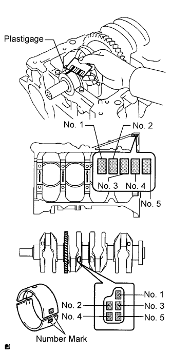 |
Measure the Plastigage at its widest point.
| Cylinder block + Crankshaft | 0 to 2 | 3 to 5 | 6 to 8 | 9 to 11 |
| Bearing to be used | "1" | "2" | "3" | "4" |
| Mark | Specified Condition |
| 0 | 59.000 to 59.002 mm (2.3228 to 2.3229 in.) |
| 1 | 59.003 to 59.004 mm (2.3230 to 2.3230 in.) |
| 2 | 59.005 to 59.006 mm (2.3230 to 2.3231 in.) |
| 3 | 59.007 to 59.009 mm (2.3231 to 2.3232 in.) |
| 4 | 59.010 to 59.011 mm (2.3232 to 2.3233 in.) |
| 5 | 59.012 to 59.013 mm (2.3233 to 2.3234 in.) |
| 6 | 59.014 to 59.016 mm (2.3234 to 2.3235 in.) |
| Mark | Specified Condition |
| 0 | 54.999 to 55.000 mm (2.1653 to 2.1654 in.) |
| 1 | 54.997 to 54.998 mm (2.1652 to 2.1653 in.) |
| 2 | 54.995 to 54.996 mm (2.1652 to 2.1652 in.) |
| 3 | 54.993 to 54.994 mm (2.1651 to 2.1651 in.) |
| 4 | 54.991 to 54.992 mm (2.1650 to 2.1650 in.) |
| 5 | 54.988 to 54.990 mm (2.1649 to 2.1650 in.) |
| Mark | Specified Condition |
| 1 | 1.993 to 1.996 mm (0.0785 to 0.0786 in.) |
| 2 | 1.997 to 1.999 mm (0.0786 to 0.0787 in.) |
| 3 | 2.000 to 2.002 mm (0.0787 to 0.0788 in.) |
| 4 | 2.003 to 2.005 mm (0.0789 to 0.0789 in.) |
| 28. INSPECT CRANKSHAFT BEARING CAP SET BOLT |
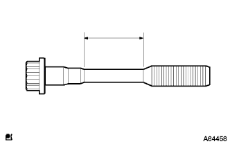 |
Using vernier calipers, measure the tension portion diameter of the bolts.