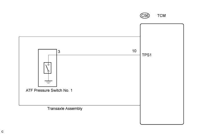
DTC P0872 Transmission Fluid Pressure Sensor / Switch "C" Circuit Low |
DTC P0873 Transmission Fluid Pressure Sensor / Switch "C" Circuit High |
| DTC No. | DTC Detecting Condition | Trouble Area |
| P0872 | ATF pressure switch No. 1 OFF is detected twice when any of the gears from 1st to 4th engages normally. |
|
| P0873 | ATF pressure switch No. 1 ON is detected twice when 5th or 6th gear engages normally. |
| 1.CHECK OTHER DTC OUTPUT (IN ADDITION TO DTC P0872 OR P0873) |
Connect the intelligent tester to the DLC3.
Turn the ignition switch on and turn the intelligent tester on.
Enter the following items: "Powertrain / ECT / DTC / Current or Pending".
Read the DTCs using the intelligent tester.
| Display (DTC output) | Proceed to |
| Only "P0873" is output | A |
| Only "P0872" is output | B |
| "P0872 or P0873" and other DTCs | C |
|
| ||||
|
| ||||
| A | |
 |
| 2.CHECK TRANSMISSION WIRE (SHORT TO GROUND) |
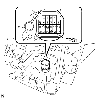 |
Remove the TCM.
Measure the resistance according to the value(s) in the table below.
| Tester Condition | Specified Condition |
| 10 (TPS1) - Body ground (Valve body assembly) | 10 kΩ or higher |
|
| ||||
| NG | |
|
| 3.CHECK ATF TEMPERATURE SENSOR ASSEMBLY (ATF PRESSURE SWITCH NO.1) |
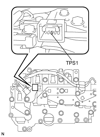 |
Disconnect the connector from the ATF temperature sensor assembly.
Measure the resistance according to the value(s) in the table below.
| Tester Condition | Specified Condition |
| 3 (TPS1) - Body ground (Valve body assembly) | 10 kΩ or higher |
|
| ||||
| OK | ||
 | ||
| ||
| 4.CHECK TRANSMISSION WIRE |
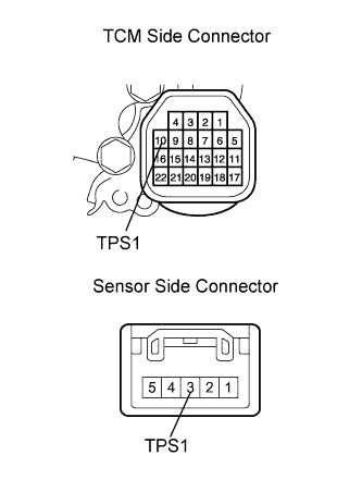 |
Remove the TCM.
Disconnect the speed sensor connector from the ATF temperature sensor assembly.
Measure the resistance according to the value(s) in the table below.
| Tester Condition | Specified Condition |
| 10 (TPS1) - 3 (TPS1) | Below 1 Ω |
| 10 (TPS1) or 3 (TPS1) - Body ground (Valve body assembly) | 10 kΩ or higher |
|
| ||||
| OK | ||
| ||
| ||

