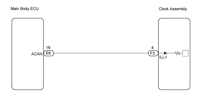
CLOCK > Clock Display Circuit |
| 1.CHECK HARNESS AND CONNECTOR (CLOCK ASSEMBLY - MAIN BODY ECU) |
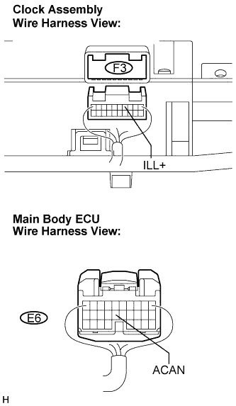 |
Disconnect the E6 and F3 connectors.
Measure the resistance according to the value(s) in the table below.
| Tester Connection | Condition | Specified Condition |
| E6-16 (ACAN) - F3-4 (ILL+) | Always | Below 1 Ω |
| F3-4 (ILL+) - Body ground | Always | 10 kΩ or higher |
|
| ||||
| OK | |
 |
| 2.INSPECT MAIN BODY ECU |
Reconnect the E6 connector.
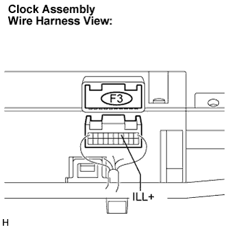 |
Measure the voltage according to the value(s) in the table below.
| Tester Connection | Condition | Specified Condition |
| F3-4 (ILL+) - Body ground | Turn the ignition switch to the ON position, cover the automatic light control sensor by hand, and light control switch TAIL/HEAD | 10 to 14 V |
|
| ||||
| OK | ||
 | ||
| ||
