COMPRESSOR AND PULLEY (for 2AZ-FE) > INSTALLATION |
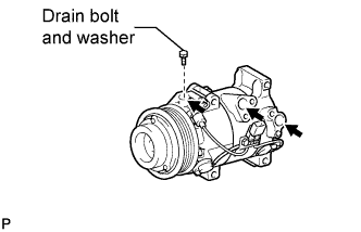
| 1. ADJUST COMPRESSOR OIL LEVEL |
![]() |
When replacing the cooler compressor assembly with a new one, gradually discharge the inert gas (helium) from the service valve, and drain the following amount of oil from the vents indicated by the arrows in the illustration before installation.
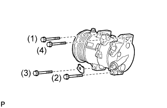
| 2. INSTALL COMPRESSOR AND PULLEY |
![]() |
Install the compressor and pulley and the engine wire harness bracket with the 4 bolts.
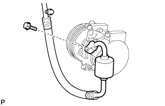
| 3. INSTALL NO. 1 COOLER REFRIGERANT SUCTION HOSE |
![]() |
Remove the attached vinyl tape from the hose.
Apply sufficient compressor oil to a new O-ring and the fitting surface of the compressor and magnetic clutch.
Install the O-ring onto the No. 1 cooler refrigerant suction hose.
Install the No. 1 cooler refrigerant suction hose onto the compressor and magnetic clutch with the bolt.
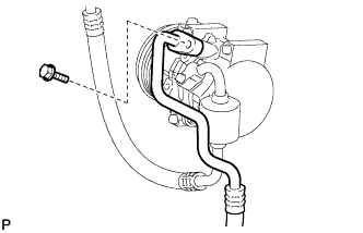
| 4. INSTALL NO. 1 COOLER REFRIGERANT DISCHARGE HOSE |
![]() |
Remove the attached vinyl tape from the hose.
Apply sufficient compressor oil to a new O-ring and the fitting surface of the compressor and magnetic clutch.
Install the O-ring onto the No. 1 cooler refrigerant discharge hose.
Install the discharge hose sub-assembly onto the compressor and magnetic clutch with the bolt.
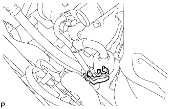
| 5. INSTALL PIPING CLAMP |
![]() |
Install the piping clamp to the No. 1 cooler refrigerant suction hose and No. 1 cooler refrigerant discharge hose.
| 6. INSTALL GENERATOR ASSEMBLY |
![]() |
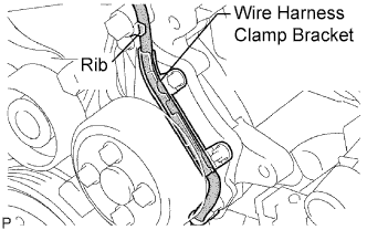
Confirm that the wire harness of the crankshaft position sensor is secured to the wire harness clamp bracket through the back of the rib of the timing chain cover.
![]() |
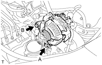
Install the generator assembly with the 2 bolts.
![]() |
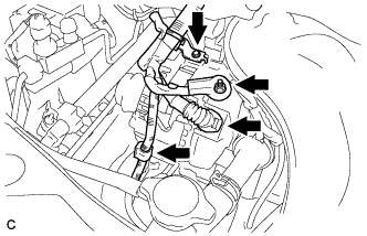
Install the generator wire to terminal B with the nut.
Install the clamp bracket with the bolt.
Attach the clamp and connect the generator connector to the generator.
| 7. INSTALL V-RIBBED BELT |
![]() |
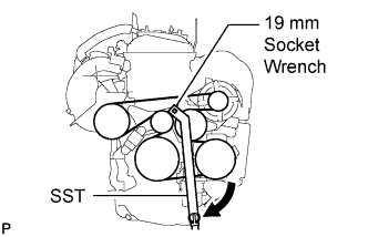
Using SST and 19 mm socket wrench, loosen the V-ribbed belt tensioner arm clockwise, then install the V-ribbed belt.
After installing the V-ribbed belt, check that it fits properly in the ribbed grooves. Check to confirm that the belt has not slipped out of the grooves on the bottom of the crank pulley by hand.
| 8. INSTALL FRONT FENDER APRON SEAL RH |
| 9. INSTALL RADIATOR HOSE OUTLET |
![]() |
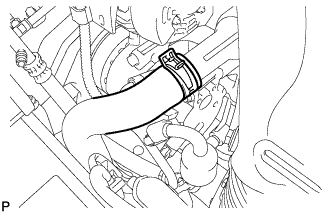
Install the radiator hose outlet and attach the clip.
| 10. CONNECT BATTERY NEGATIVE TERMINAL |
| 11. ADD ENGINE COOLANT |
Close the radiator drain cock plug and 2 cylinder block drain cock plugs.
Slowly fill the radiator with TOYOTA Super Long Life Coolant (SLLC).
Slowly pour coolant into the radiator reservoir tank until it reaches the FULL line.
Press the inlet and outlet radiator hoses several times by hand, and then check the level of the coolant.
If the coolant level is low, add coolant.
Install the radiator cap sub-assembly and reservoir tank cap.
Start the engine, and warm it up.
Stop the engine, and wait until the engine coolant cools down.
Add engine coolant to the FULL line on the radiator reservoir.
| 12. CHECK FOR ENGINE COOLANT LEAKS |
| 13. INSTALL ENGINE UNDER COVER RH |
| 14. INSTALL FRONT WHEEL RH |
| 15. CHARGE WITH REFRIGERANT |
Perform vacuum purging using a vacuum pump.
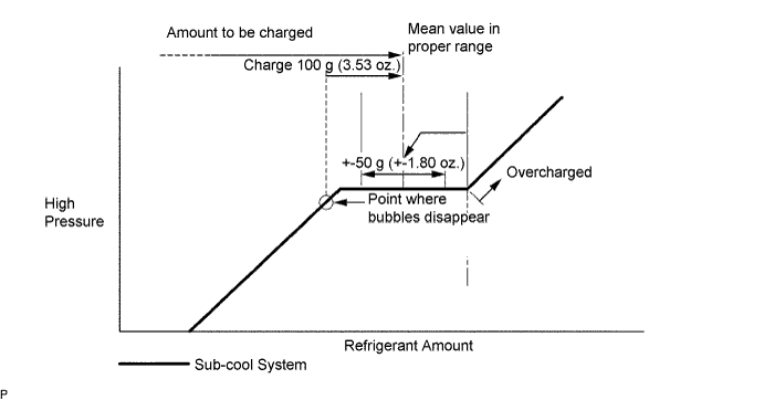
Charge with refrigerant HFC-134a (R134a).

| 16. WARM UP ENGINE |
Keep the A/C switch on for at least 2 minutes to warm up the compressor.
| 17. CHECK FOR REFRIGERANT LEAKS |
After recharging with refrigerant gas, check for leakage of refrigerant gas using a halogen leak detector.
Carry out the test under the following conditions:
![]() |
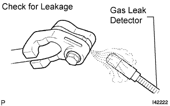
Using a gas leak detector, check for leakage from the refrigerant lines.
![]() |
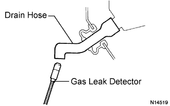
Bring the gas leak detector close to the drain hose with the detector's power off, and then turn the detector on.
If a gas leak is not detected from the drain hose, remove the blower motor control from the cooling unit. Insert the gas leak detector sensor into the unit and perform the test.
Disconnect the pressure switch connector and leave it for approximately 20 minutes. Bring the gas leak detector close to the pressure switch and perform the test.