 |
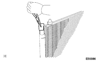
Using pliers, install the cooler dryer to the modulator.
CONDENSER > INSTALLATION |
| 1. INSTALL COOLER DRYER |
|
Using pliers, install the cooler dryer to the modulator.
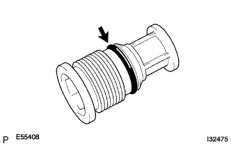 |
Apply sufficient compressor oil to an O-ring and cap fitting surface.
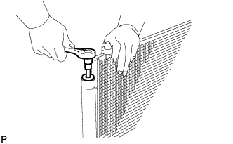 |
Using a straight hexagon wrench 14 mm, install the cap to the cooler condenser core.
| 2. INSTALL COOLER CONDENSER ASSEMBLY |
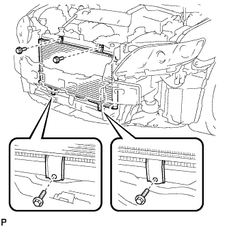 |
Install the cooler condenser assembly with the 4 bolts.
| 3. INSTALL COOLER REFRIGERANT DISCHARGE PIPE |
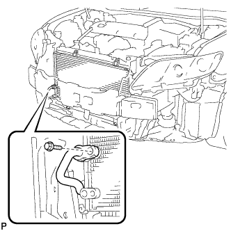 |
Remove the attached vinyl tape from the pipe and the connecting part of the cooler condenser assembly.
Sufficiently apply compressor oil to a new O-ring and the fitting surface of the pipe joint.
Install the O-ring on the cooler refrigerant discharge pipe.
| 4. INSTALL AIR CONDITIONING TUBE AND ACCESSORY |
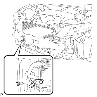 |
Remove the attached vinyl tape from the tube and the connecting part of the cooler condenser assembly.
Sufficiently apply compressor oil to a new O-ring and the fitting surface of the tube joint.
Install the O-ring on the air conditioning tube assembly.
Install the air conditioning tube assembly on the cooler condenser assembly with the bolt.
| 5. INSTALL HOOD LOCK SUPPORT SUB-ASSEMBLY |
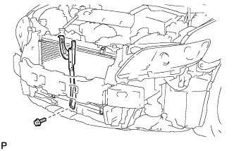 |
Install the hood lock support sub-assembly with the bolt.
| 6. INSTALL RADIATOR SUPPORT UPPER |
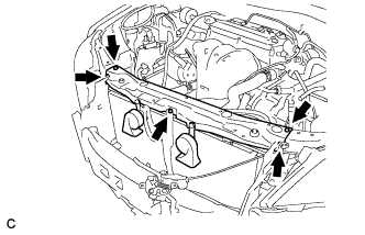 |
Install the radiator support upper with the 5 bolts.
For LHD:
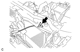 |
Install the hood lock control cable assembly to the radiator support upper with the clamp.
For RHD:
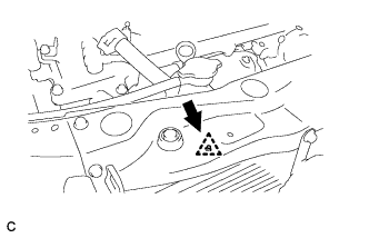 |
Install the hood lock control cable assembly to the radiator support upper with the clamp.
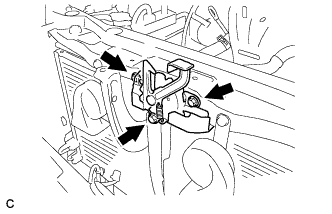 |
Install the hood lock assembly to the radiator support upper with the 3 bolts.
Connect the horn connector.
| 7. INSTALL FRONT BUMPER ASSEMBLY |
w/ Headlight Cleaner System:
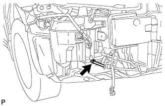 |
Connect the headlight cleaner washer hose.
Connect each connector.
w/ TOYOTA Parking Assist-sensor System:
Connect the No. 1 ultrasonic sensor connector and engage the clamp.
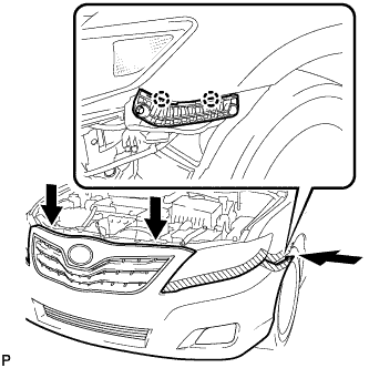 |
Engage the 2 claws.
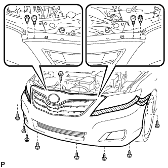 |
Install the front bumper assembly with the 8 screws, 2 clips, 2 radiator grille protectors and bolt.
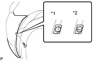 |
Install the pin hold clip.
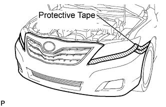 |
Remove the applied protective tape on the front bumper assembly.
| 8. INSTALL NO. 1 AIR CLEANER INLET (for 2GR-FE) |
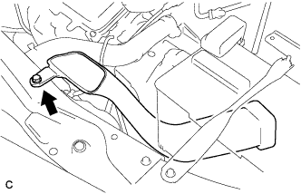 |
Install the No. 1 air cleaner inlet with the bolt.
| 9. INSTALL AIR CLEANER INLET ASSEMBLY (for 2AZ-FE) |
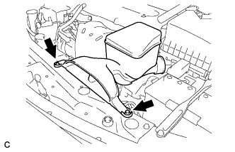 |
Install the air cleaner inlet with the 2 bolts.
| 10. INSTALL AIR CLEANER INLET SUB-ASSEMBLY (for 2GR-FE) |
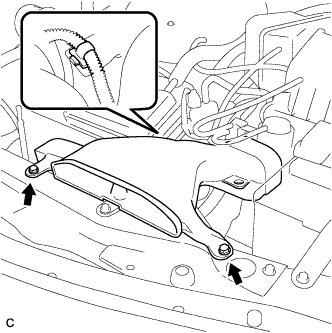 |
Install the air cleaner inlet with the clamp and 2 bolts.
| 11. INSTALL AIR CLEANER CAP SUB-ASSEMBLY (for 2AZ-FE) |
Install the air cleaner filter element onto the air cleaner case.
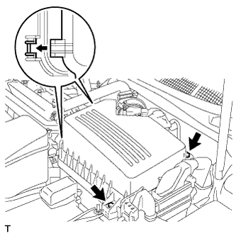 |
Insert the hinges. Install the air cleaner cap sub-assembly with the 2 bolts.
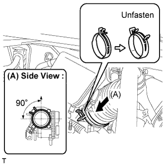 |
Align the matchmarks of the No. 1 air cleaner hose and throttle body, and then connect the air cleaner hose No. 1 to the throttle body and unfasten the No. 1 air cleaner hose clamp.
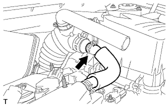 |
Connect the No. 2 ventilation hose to the air cleaner hose.
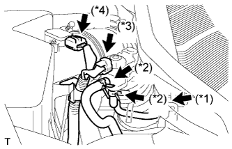 |
Connect the purge line hose to the clamp (*1).
Connect the 2 purge VSV vacuum hoses (*2).
Connect the purge VSV connector (*3).
Connect the mass air flow meter connector (*4).
| 12. INSTALL AIR CLEANER CAP SUB-ASSEMBLY (for 2GR-FE) |
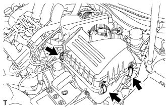 |
Install the air cleaner cap sub-assembly, and connect the 3 bands.
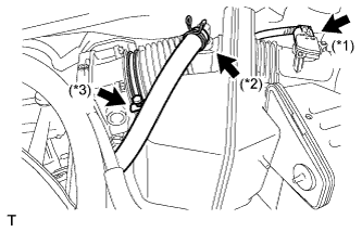 |
Connect the mass air flow meter connector (*1).
Connect the No. 2 ventilation hose (*2).
Connect the hose band (*3).
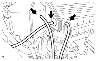 |
Connect the 3 vacuum hoses.
| 13. INSTALL COOL AIR INTAKE DUCT SEAL (for 2GR-FE) |
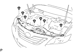 |
Install the cool air intake duct seal with the 7 clips.
| 14. INSTALL V-BANK COVER SUB-ASSEMBLY (for 2GR-FE) |
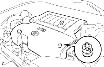 |
Engage the 3 retainers to install the V-bank cover.
| 15. ADD ENGINE COOLANT (for 2AZ-FE) |
Close the radiator drain cock plug and 2 cylinder block drain cock plugs.
Slowly fill the radiator with TOYOTA Super Long Life Coolant (SLLC).
Slowly pour coolant into the radiator reservoir tank until it reaches the FULL line.
Press the inlet and outlet radiator hoses several times by hand, and then check the level of the coolant.
If the coolant level is low, add coolant.
Install the radiator cap sub-assembly and reservoir tank cap.
Start the engine, and warm it up.
Stop the engine, and wait until the engine coolant cools down.
Add engine coolant to the FULL line on the radiator reservoir.
| 16. ADD ENGINE COOLANT (for 2GR-FE) |
Close the radiator drain cock plug and 2 cylinder block drain cock plugs.
Slowly fill the radiator with TOYOTA Super Long Life Coolant (SLLC).
Slowly pour coolant into the radiator reservoir tank until it reaches the FULL line.
Press the inlet and outlet radiator hoses several times by hand, and then check the level of the coolant.
If the coolant level is low, add coolant.
Install the radiator cap sub-assembly and reservoir tank cap.
Start the engine, and warm it up.
Stop the engine, and wait until the engine coolant cools down.
Add engine coolant to the FULL line on the radiator reservoir.
| 17. CHECK FOR ENGINE COOLANT LEAKS |
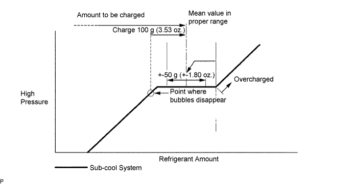
| 18. CHARGE WITH REFRIGERANT |
Perform vacuum purging using a vacuum pump.
Charge with refrigerant HFC-134a (R134a).
| 19. WARM UP ENGINE |
Keep the A/C switch on for at least 2 minutes to warm up the compressor.
| 20. CHECK FOR REFRIGERANT LEAKS |
After recharging with refrigerant gas, check for leakage of refrigerant gas using a halogen leak detector.
Carry out the test under the following conditions:
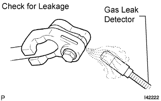 |
Using a gas leak detector, check for leakage from the refrigerant lines.
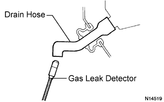 |
Bring the gas leak detector close to the drain hose with the detector's power off, and then turn the detector on.
If a gas leak is not detected from the drain hose, remove the blower motor control from the cooling unit. Insert the gas leak detector sensor into the unit and perform the test.
Disconnect the pressure switch connector and leave it for approximately 20 minutes. Bring the gas leak detector close to the pressure switch and perform the test.
| 21. VEHICLE PREPARATION FOR FOG LIGHT AIM ADJUSTMEN (w/ Fog Light) |
Prepare the vehicle:
| 22. PREPARATION FOR FOG LIGHT AIMING (w/ Fog Light) |
 |
Prepare the vehicle:
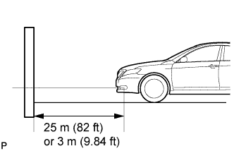
Prepare a piece of thick white paper (approximately 2 m (6.6 ft) (height) x 4 m (13.1 ft) (width)) to use as a screen.
Draw a vertical line down the center of screen (V line).
Set the screen as shown in the illustration.
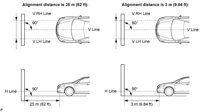
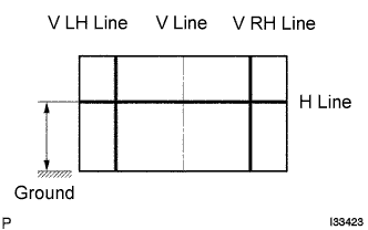 |
Draw base lines (H, V LH, and V RH lines) on the screen as shown in the illustration.
H Line (Fog light height):
Draw a horizontal line across the screen so that it passes through the center marks. The H line should be at the same height as the fog light bulb center marks of the low-beam fog lights.
V LH Line, V RH Line (Center mark position of left-hand (LH) and right-hand (RH) fog lights):
Draw two vertical lines so that they intersect the H line at each center mark.
| 23. FOG LIGHT AIMING INSPECTION (w/ Fog Light) |
Cover the fog light or disconnect the connector of the fog light on the opposite side to prevent light from the fog light that is not being inspected from affecting the fog light aiming inspection.
Start the engine.
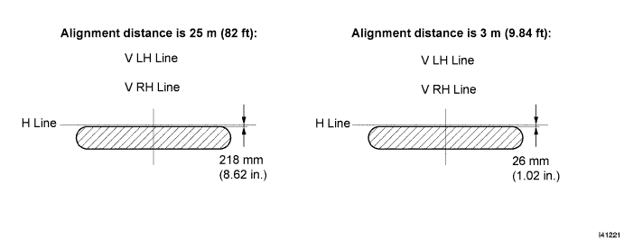
Turn on the fog light and check if the cut off line falls within the specified area in the following illustration.
| 24. FOG LIGHT AIMING ADJUSTMENT (w/ Fog Light) |
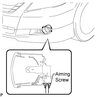 |
Adjust the aim vertically:
Adjust the aim of each fog light to the specified range by turning each aiming screw with a screwdriver.