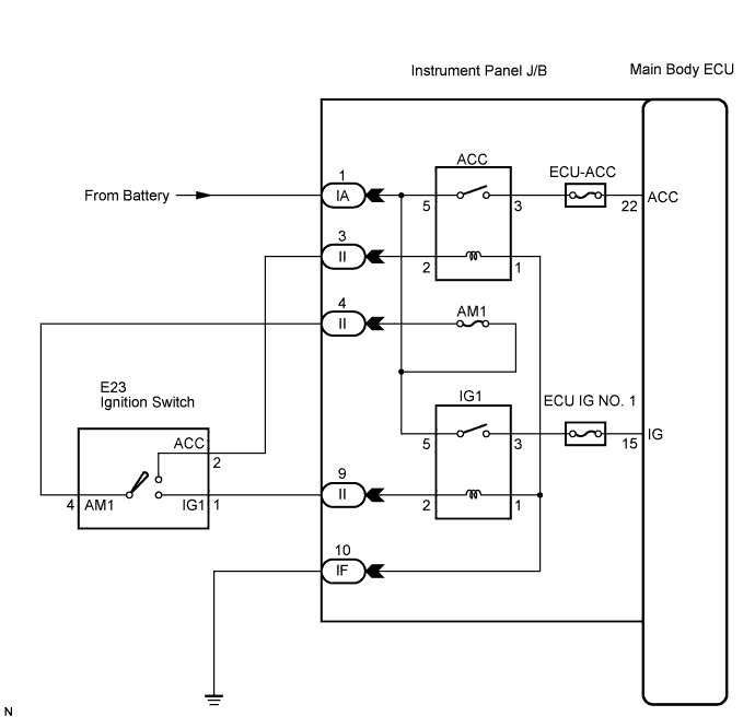
THEFT DETERRENT SYSTEM (w/o Entry and Start System) > Ignition Switch Circuit |
| 1.READ VALUE USING INTELLIGENT TESTER |
Connect the intelligent tester (with CAN VIM) to the DLC3.
Turn the ignition switch to the ON position.
Turn the intelligent tester main switch on.
Select the item below in the Data List and read the display on the intelligent tester.
| Item | Test Details | Diagnostic Note |
| IG SW | ignition switch ON signal ON/OFF | - |
| ACC SW | ignition switch ACC signal ON/OFF | - |
|
| ||||
| OK | ||
 | ||
| ||
| 2.CHECK HARNESS AND CONNECTOR (BATTERY - INSTRUMENT PANEL J/B) |
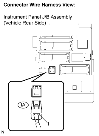 |
Disconnect the IA J/B connector.
Measure the voltage according to the value(s) in the table below.
| Tester Connection | Condition | Specified Condition |
| IA-1 - Body ground | Ignition switch ON | 10 to 14 V |
|
| ||||
| OK | |
 |
| 3.INSPECT IGNITION OR STARTER SWITCH ASSEMBLY |
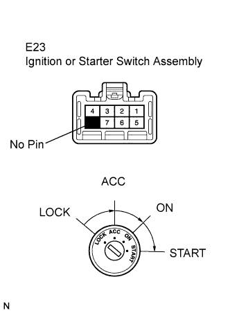 |
Disconnect the E23 switch connector from the ignition switch.
Measure the resistance according to the value(s) in the table below.
| Tester Connection | Condition | Specified Condition |
| 1 - 4 | Ignition switch ON | Below 1 Ω |
| 2 - 4 | Ignition switch ACC | Below 1 Ω |
|
| ||||
| OK | |
|
| 4.CHECK HARNESS AND CONNECTOR (INSTRUMENT PANEL J/B - INSTRUMENT PANEL J/B) |
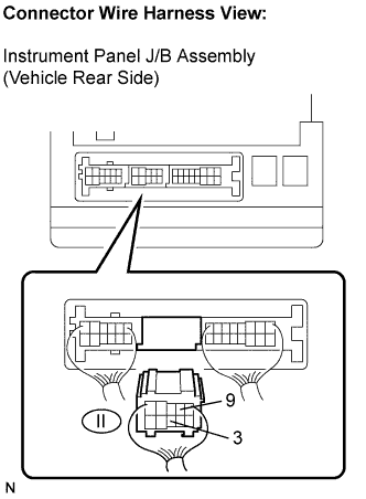 |
Disconnect the II J/B connector.
Measure the resistance according to the value(s) in the table below.
| Tester Connection | Condition | Specified Condition |
| II-4 - II-9 | Ignition switch ON | Below 1 Ω |
| II-4 - II-3 | Ignition switch ACC | Below 1 Ω |
|
| ||||
| OK | |
|
| 5.CHECK HARNESS AND CONNECTOR (INSTRUMENT PANEL J/B - BODY GROUND) |
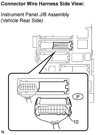 |
Disconnect the IF J/B connector.
Measure the resistance according to the value(s) in the table below.
| Tester Connection | Specified Condition |
| IF-10 - Body ground | Below 1 Ω |
|
| ||||
| OK | ||
| ||
| ||

