LIGHTING SYSTEM > SYSTEM DESCRIPTION |
| MANUAL LIGHT CONTROL SYSTEM |
The main body ECU controls this system based on the signals listed below.
| Input | Output | Lights that illuminate |
| Light control switch TAIL signal | Taillight relay drive signal |
|
| Light control switch HEAD signal | Headlight relay drive signal | Low beam headlights |
| AUTOMATIC LIGHT CONTROL SYSTEM |
The main body ECU controls this system based on the signals listed below.
| Input | Output | Lights that illuminate |
|
|
|
| LIGHT AUTO TURN OFF SYSTEM |
The main body ECU controls this system based on the signals listed below.
| Input | Output | Lights that operate |
|
|
|
| ILLUMINATED ENTRY SYSTEM |
The main body ECU controls this system. The operation and condition of the illuminated entry system are described below.
| Operation | Condition |
| Fade in | When either of the following conditions is met, the interior light and ignition key cylinder light fade in:
|
| Fade out immediately | When either of the following conditions is met, the interior light and ignition key cylinder light fade out:
|
| Illuminate for approximately 15 seconds, and then fade out | Any doors are closed when the ignition switch is off. |
| Fade out (Battery saving) | When the following conditions are met, the interior light and ignition key cylinder light fade out:
|
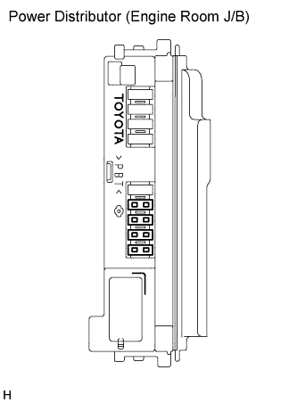
| POWER DISTRIBUTOR |
![]() |
The power distributor (engine room J/B assembly) is installed in the engine room R/B. The low beam headlight relays and high beam headlight relay are installed in the power distributor.
When a short malfunction occurs between the power distributor and high beam headlight bulbs, the fail-safe function operates.
When the fail-safe function operates, the power distributor stops the operation of the high beam headlight relay.
| HID HEADLIGHT SYSTEM |
Discharge bulbs have the following feature:
This system consists of discharge bulbs and the light control ECU. The light control ECU is installed in the headlight assembly.
The light control ECUs transform the voltage that is input from the battery to a high voltage of up to 20,000 V and applies it to the discharge bulbs in order to illuminate them.
A fail-safe function is provided as a countermeasure against the high voltage that is generated in case that a problem occurs in the headlight system.
| AUTOMATIC HEADLIGHT BEAM LEVEL CONTROL SYSTEM |
General
Function and construction of components
| Components | Function and Construction |
| Rear height control sensor | Detects the amount of vehicle height. |
| Combination meter |
|
| Headlight leveling motor | Based on the signals received from the headlight beam level control ECU, each motor moves the reflector in the headlight to vary its LO beam. |
| DLC3 | The height control sensor signal initialization and headlight leveling motor operation check can be performed via the DLC3. |
| Headlight beam level control ECU |
|
![]() |
Fail-safe function
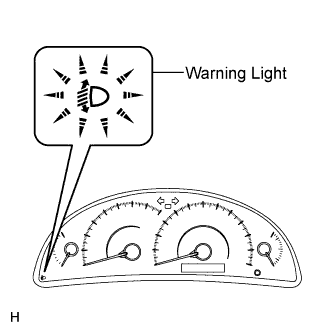
The headlight beam level control ECU operates in the fail-safe mode if an abnormal condition has been detected, and illuminates the automatic headlight leveling system warning light in the combination meter when a malfunction is detected in the height control sensor.
| MANUAL HEADLIGHT BEAM LEVEL CONTROL SYSTEM |
When the vehicle posture changes in accordance with the number (weight) of passengers and volume of luggage, this system enables the adjustment of the LO beam level (11-step) of the headlights manually to the appropriate level based on the position of the headlight leveling switch.