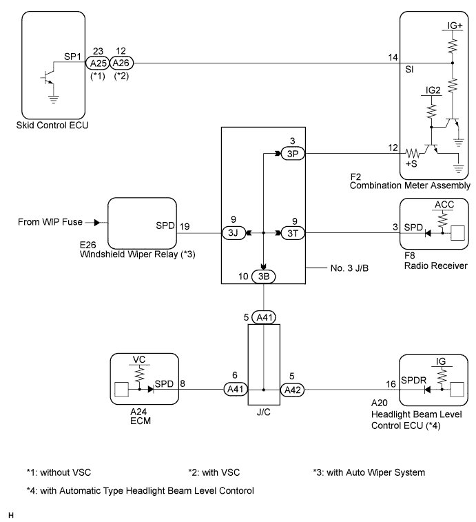
LIGHTING SYSTEM > Speed Signal Circuit |
| for 2AZ-FE: |
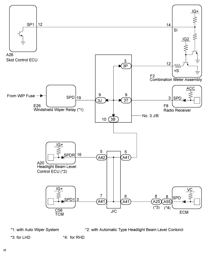
| for 2GR-FE: |
| 1.CHECK COMBINATION METER SYSTEM |
The circuits that send vehicle speed signals to this system are inspected in the meter system (Click here).
During inspection for the meter section, if there is an instruction that indicates to go back inspections for each system, proceed to the next step.
| NEXT | |
 |
| 2.CHECK HARNESS AND CONNECTOR (HEADLIGHT BEAM LEVEL CONTROL ECU - COMBINATION METER) |
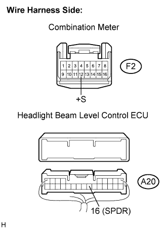 |
Disconnect the F2 combination meter connector.
Disconnect the A20 headlight beam level control ECU connector.
Measure the resistance according to the value(s) in the table below.
| Tester connection | Condition | Specified condition |
| A20-16 (SPDR) - F2-12 (+S) | Always | Below 1 Ω |
| A20-16 (SPDR) - Body ground | Always | 10 kΩ or higher |
|
| ||||
| OK | ||
 | ||
| ||
| 3.CHECK HARNESS AND CONNECTOR (HEADLIGHT BEAM LEVEL CONTROL ECU - NO. 3 J/B) |
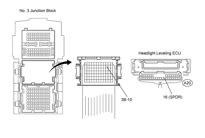
Disconnect the No. 3 J/B connector.
Measure the resistance according to the value(s) in the table below.
| Tester Connection | Condition | Specified Condition |
| 3B-10 - A20-16 (SPDR) | Always | Below 1 Ω |
|
| ||||
| OK | ||
| ||
| ||

