LIN COMMUNICATION SYSTEM > TERMINALS OF ECU |
| CHECK MAIN BODY ECU (INSTRUMENT PANEL JUNCTION BLOCK) |
Disconnect the ID and IF instrument panel junction block connectors.
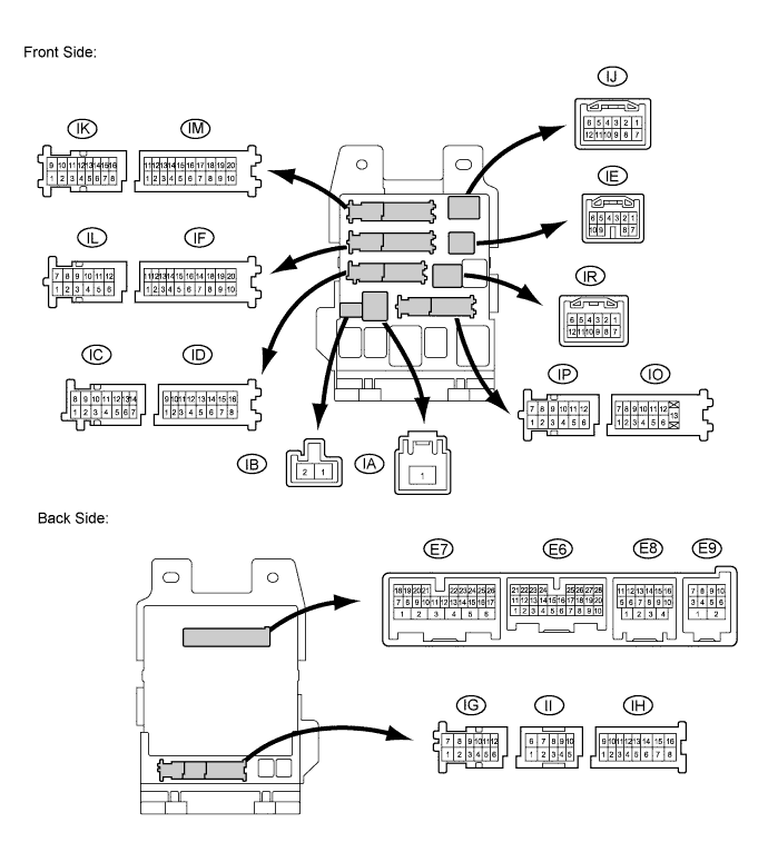
Measure the voltage and resistance according to the value(s) in the table below.
| Terminal No. (Symbols) | Wiring Color | Terminal Description | Condition | Specified Condition |
| ID-10 (BECU) - Body ground | O - Body ground | Battery power supply | Always | 11 to 14 V |
| IF-10 (GND1) - Body ground | W-B - Body ground | Ground | Always | Below 1 Ω |
Reconnect the ID and IF instrument panel junction block connectors.
Measure the pulse according to the value(s) in the table below.
| Terminal No. (Symbols) | Wiring Color | Terminal Description | Condition | Specified Condition |
| E8-10 (LIN2) - IF-10 (GND1) | P - W-B | LIN Communication line | Ignition switch ON | Pulse generation |

| CHECK POWER WINDOW REGULATOR MOTOR (DRIVER SIDE) |
Disconnect the I5*1 or H10*2 motor connector.

Measure the voltage and resistance according to the value(s) in the table below.
| Terminal No. (Symbols) | Wiring Color | Terminal Description | Condition | Specified Condition |
| I5-2 (B) - I5-1 (E)*1 H10-2 (B) - H10-1 (E)*2 | W - W-B | Battery power supply | Always | 11 to 14 V |
| I5-1 (E) - Body ground*1 H10-1 (E) - Body ground*2 | W-B - Body ground | Ground | Always | Below 1 Ω |
Reconnect the I5*1 or H10*2 motor connector.
Measure the pulse according to the value(s) in the table below.
| Terminal No. (Symbols) | Wiring Color | Terminal Description | Condition | Specified Condition |
| I5-9 (LIN) - I5-1 (E)*1 H10-9 (LIN) - H10-1 (E)*2 | P - W-B | LIN Communication line | Ignition switch ON | Pulse generation |

| CHECK SLIDING ROOF ECU (SLIDING ROOF DRIVE GEAR SUB-ASSEMBLY)* |
Disconnect the Q12 ECU connector.

Measure the voltage and resistance according to the value(s) in the table below.
| Terminal No. (Symbols) | Wiring Color | Terminal Description | Condition | Specified Condition |
| Q12-1 (B) - Q12-2 (E) | B - W-B | Battery power supply | Always | 11 to 14 V |
| Q12-2 (E) - Body ground | W-B - Body ground | Ground | Always | Below 1 Ω |
Reconnect the Q12 ECU connector.
Measure the pulse according to the value(s) in the table below.
| Terminal No. (Symbols) | Wiring Color | Terminal Description | Condition | Specified Condition |
| Q12-4 (MPX1) - Q12-2 (E) | P - W-B | LIN Communication line | Ignition switch ON | Pulse generation |