SEAT POWER SEAT CONTROL SYSTEM CONTROL SEAT CONTROL
SYSTEM CONTROL
Seat Position Detection Method
Power Seats with Memory Function
The Hall IC installed on the power seat motor generates pulses corresponding to the speed of the motor. These pulses are then picked up by the position control ECU and switch assembly (position control ECU) in order to detect the seat position.
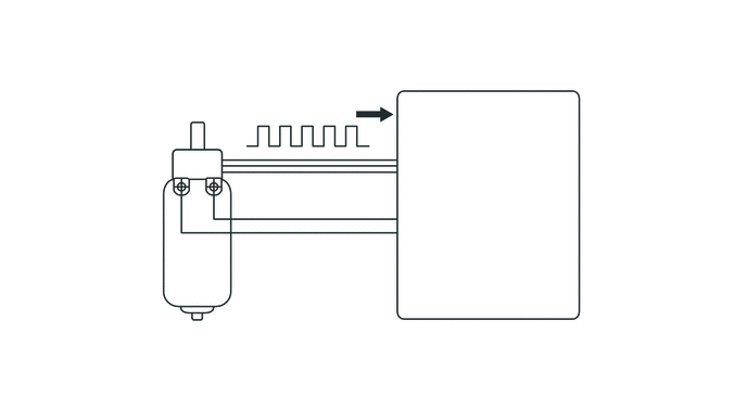
| *1 | Power Seat Motor | *2 | Position Control ECU and Switch Assembly (Position Control ECU) |
| *3 | Hall IC | - | - |
| *a | Current pulsations generated by motor | - | - |
Power Seats without Memory Function
A pulse generation circuit in the position control ECU and switch assembly (position control ECU) converts the current pulsations that are generated by the rotation of the motor into pulse signals. These signals are then used in order to detect the seat position.
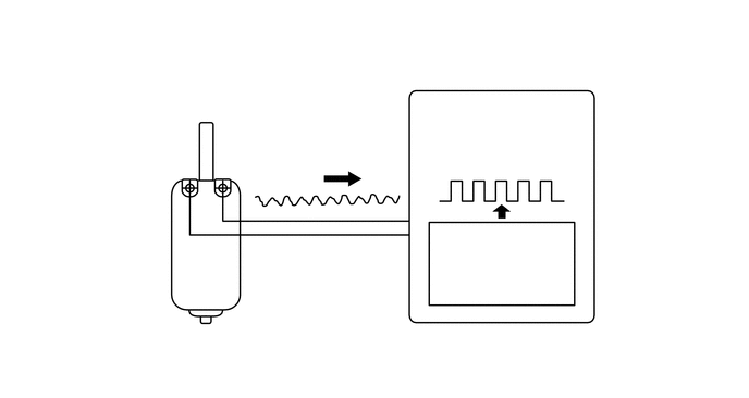
| *1 | Power Seat Motor | *2 | Position Control ECU and Switch Assembly (Position Control ECU) |
| *a | Current pulsations generated by motor | *b | Pulses after conversion |
| *c | Pulse Generation Circuit | - | - |
Memory Function for Driver Seat
The memory, recall and memory call conditions of the memory function are as follows:
| Function | Condition | Operation | Action |
|---|---|---|---|
| Memory | Engine switch is on (IG). | Switch 1 or 2 is pressed while the "SET" button is pressed. | ·
Memorizes the seat position when switch 1 or 2 is pressed. ·
When the memory setting is completed, the buzzer will sound for 0.5 seconds. |
| Switch 1 or 2 is pressed within 3 seconds after the "SET" button is pressed. | |||
| Recall | ·
Engine switch is on (IG). ·
The shift lever is in P. ·
Memory switch is off. ·
Seat position is memorized. |
Switch 1 or 2 is pressed. | Recalls the seat position that was memorized in the position control ECU and switch assembly. |
·
Engine switch is off. ·
Memory switch is off. ·
Seat position is memorized. ·
Driver door is opened. |
Switch 1 or 2 is pressed within 180 seconds after engine switch is turned off and driver door is opened. | ||
·
Engine switch is off. ·
Memory switch is off. ·
Seat position is memorized. ·
Open driver door is closed. |
Switch 1 or 2 is pressed within 60 seconds after engine switch is turned off and the open driver door is closed. | ||
| Memory Call | ·
A key ID is registered to switch 1 or 2. ·
Engine switch is off. ·
Inside of the outside door handle is touched or the key unlock button is pushed, and then the driver door is opened. |
The seat automatically moves rearward up to 50 mm (1.97 in.)* from the memorized seat position. | |
Engine switch is on (ACC) or on (IG). |
The seat automatically returns to the memorized seat position. | ||
*: Seat movement distance can be changed using the customized body electronics system. For details, refer to the Repair Manual.
FUNCTION
Memory Function for Driver Seat
The power seat control system has the following functions:
| Function | Outline | |
|---|---|---|
| Power Control | The fore-and-aft slide, reclining, front vertical, lifter and lumbar support can be adjusted using the power seat switch. | |
| Memory | Memory | The memory function can memorize 2 different seat positions. |
| Recall | The recall function can recall 2 different memorized seat positions. | |
| Memory Call | The memory call function, which utilizes the key IDs, is used to memorize and retrieve the optimal driving positions for a person possessing the key. | |
The memory function works in combination with the following systems, ensuring usability and enabling easy entering or exiting of the vehicle.
| System | Outline |
|---|---|
| Outside Rear View Mirror System | The outer mirror control ECU memorizes the outside rear view mirror positions and recalls them when all conditions are met. |
DIAGNOSIS
The position control ECU and switch assembly (position control ECU) has a diagnosis function. It stores a record of any power seat control system failures in its memory in the form of Diagnostic Trouble Codes (DTCs).
The position control ECU and switch assembly (position control ECU) outputs malfunction data and 5-digit DTCs to the intelligent tester.
The 5-digit DTCs can be read after connecting the intelligent tester to the DLC3. For details, refer to the Repair Manual.