Home › Vehicle Interior › HEATING / AIR CONDITIONING › AIR CONDITIONING SYSTEM
NM19V0EQ _58 Vehicle Interior _014277 HEATING / AIR CONDITIONING _0072887 AIR CONDITIONING SYSTEM DE DETAILS F

HEATING / AIR CONDITIONING  AIR CONDITIONING SYSTEM  DETAILS  COMPRESSOR WITH PULLEY  


CONSTRUCTION


a.

The compressor with pulley assembly is a continuously variable capacity type air conditioning compressor. Its capacity can be varied in accordance with the cooling load of the air conditioning system.


b.

The compressor with pulley assembly consists of a pulley, shaft, lug plate, swash plate, piston, shoe, crank chamber, cylinder, air conditioning lock sensor, solenoid valve with built-in Crank chamber to Suction passage (CS) valve, air conditioning mass flow sensor, oil separator and variable suction side throttle.


c.

The oil separator consists of an oil separator chamber and an oil separator cylinder.
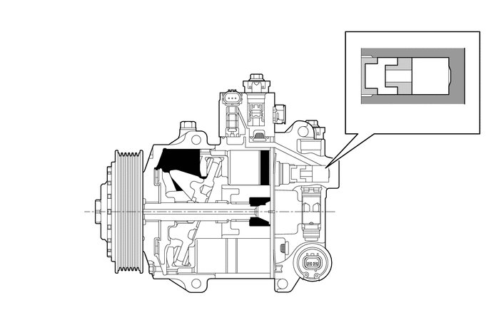
Y113414
3.573,3.01 3.573,4.49 true 4.573,3.844 4.573,4.479 true 4.635,3.042 5.396,3.042 true 1,2.75 1.51,2.75 true 2.625,4.5 2.625,3.781 true 5.917,1.292 5.917,1.719 true 5.49,1.104 5.49,1.719 true 2.406,2.531 2.094,1.479 2.094,1.479 1.906,1.479 true 2.625,2.198 2.302,1.156 2.302,1.156 2.115,1.156 true 3.885,2.229 4.208,1.188 4.208,1.188 4.396,1.188 true 3.385,1.396 3.146,0.656 3.146,0.656 3.01,0.656 true 3.031,2.313 2.615,0.948 2.615,0.948 2.365,0.948 true 3.573,2.271 3.99,0.906 3.99,0.906 4.24,0.906 true 1.729,1.406 1.938,1.594 0.208,0.188 10 false *2 1.917,1.063 2.125,1.25 0.208,0.188 10 false *3 2.198,0.865 2.406,1.052 0.208,0.188 10 false *4 2.552,4.521 2.76,4.708 0.208,0.188 10 false *5 4.302,0.823 4.51,1.01 0.208,0.188 10 false *6 4.427,1.125 4.635,1.313 0.208,0.188 10 false *7 4.521,4.5 4.844,4.688 0.323,0.188 10 false *8 3.51,4.51 3.781,4.698 0.271,0.188 10 false *9 2.771,0.563 3.042,0.75 0.271,0.188 10 false *10 5.135,0.49 5.406,0.677 0.271,0.188 10 false *11 5.385,1.75 5.656,1.938 0.271,0.188 10 false *12 5.813,1.75 6.083,1.938 0.271,0.188 10 false *13 5.417,2.948 5.688,3.135 0.271,0.188 10 false *14 0.823,2.688 1.021,2.875 0.198,0.188 10 false *1
*1 Pulley *2 Lug Plate
*3 Crank Chamber *4 Shoe
*5 Swash Plate *6 Piston
*7 Cylinder *8 Solenoid Valve with Built-in CS Valve
*9 Shaft *10 Air Conditioning Mass Flow Sensor
*11 Oil Separator *12 Oil Separator Chamber
*13 Oil Separator Cylinder *14 Variable Suction Side Throttle


d.

The plastic DL pulley contains a damper mechanism to absorb the torque fluctuations of the engine and a limiter mechanism to protect the drive belt in case the compressor locks. If the compressor locks, the limiter integrated into the pulley breaks, disconnecting the pulley from the compressor. To reduce weight, the pulley portion is made of plastic.


e.

If the compressor locks, the steel with magnetic clutch pulley turns the magnetic clutch off to protect the drive belt and separates the pulley from the compressor.
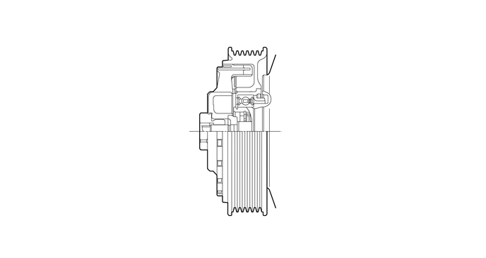
Y113415
3.698,1.885 4.656,1.885 true 2.427,1.188 3.594,1.188 true 2.438,1.708 3.042,1.708 true 3.594,0.771 3.49,0.323 3.49,0.323 3.281,0.323 true 3.115,0.25 3.333,0.438 0.219,0.188 10 false *1 2.281,1.625 2.5,1.813 0.219,0.188 10 false *4 4.688,1.802 4.896,1.99 0.208,0.188 10 false *2 2.26,1.094 2.469,1.281 0.208,0.188 10 false *3
*1 Pulley Portion *2 Shaft
*3 Damper *4 Limiter


OPERATION


a.

Variable Capacity Operation

i.

A solenoid valve is connected to the suction passage, the discharge passage and the crank chamber passage.


ii.

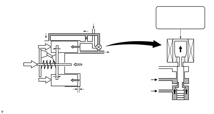
The solenoid valve operates under duty cycle control in accordance with the signals from the air conditioning amplifier assembly.
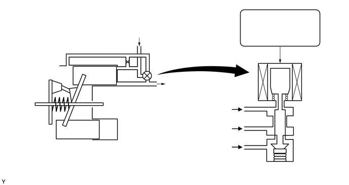
Y106791
2.646,0.552 3.188,1.01 0.542,0.458 10 Suction 3.667,2.156 4.802,2.479 1.135,0.323 10 Suction Pressure 3.438,1.646 4.167,2.104 0.729,0.458 10 Discharge 3.51,2.563 4.917,2.885 1.406,0.323 10 Discharge Pressure 1.458,2.469 2.052,2.865 0.594,0.396 10 Piston 1.844,1.396 2.438,1.792 0.594,0.396 10 Piston 0.365,1.354 1.719,1.75 1.354,0.396 10 Crank Chamber 3.188,2.927 4.813,3.292 1.625,0.365 10 Crank Chamber Pressure 5.333,3.354 6.479,3.677 1.146,0.323 10 Solenoid Valve 5.198,0.281 6.406,0.99 1.208,0.708 10 Air Conditioning Amplifier Assembly


iii.

When the solenoid valve closes (solenoid coil is energized), a difference in pressure is created and the pressure in the crank chamber decreases. Then, the pressure that is applied to the right side of the piston becomes greater than the pressure that is applied to the left side of the piston. This compresses the spring and tilts the lug plate. As a result, the piston stroke increases and the discharge capacity increases.
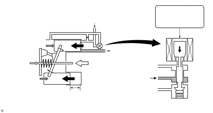
Y106792
1.052,2.135 1.052,2.885 true 3.802,2.531 5.104,2.854 1.302,0.323 10 Discharge Pressure 3.74,1.604 4.49,1.927 0.75,0.323 10 Discharge 5.625,3.375 6.75,3.583 1.125,0.208 10 Solenoid Valve 5.51,0.219 6.719,0.927 1.208,0.708 10 Air Conditioning Amplifier Assembly 2.948,0.51 3.49,0.969 0.542,0.458 10 Suction 0.198,2.969 1.844,3.49 1.646,0.521 10 Crank Chamber Pressure + Spring Force 1.979,3.115 3.604,3.635 1.625,0.521 10 Piston Stroke: Large


iv.

When the solenoid valve opens (solenoid coil is not energized), the difference in pressure disappears. Then, the pressure that is applied to the left side of the piston becomes the same as the pressure that is applied to the right side of the piston. Thus, the spring elongates and eliminates the tilt of the lug plate. As a result, the piston stroke is small, decreasing the discharge capacity.
Y106793
0.896,2.167 0.896,2.917 true 3.719,1.667 4.448,2.125 0.729,0.458 10 Discharge 3.792,2.563 5.094,2.885 1.302,0.323 10 Discharge Pressure 3.469,2.938 5.094,3.302 1.625,0.365 10 Crank Chamber Pressure 5.552,3.365 6.583,3.583 1.031,0.219 10 Solenoid Valve 5.5,0.219 6.708,0.927 1.208,0.708 10 Air Conditioning Amplifier Assembly 2.917,0.5 3.458,0.958 0.542,0.458 10 Suction 0.208,3.042 1.813,3.563 1.604,0.521 10 Crank Chamber Pressure + Spring Force 1.979,3.135 3.604,3.656 1.625,0.521 10 Piston Stroke: Small


b.

Air Conditioning Mass Flow Sensor Operation

i.

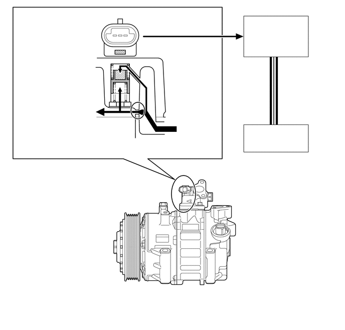
Using a spool that changes its position according to the amount of refrigerant flow, the air conditioning mass flow sensor detects the amount of refrigerant flow.


ii.

The air conditioning mass flow sensor outputs a voltage by converting the change of magnetic flux that occurs due to the magnet that is installed on the spool.


iii.

The spool changes its position according to the pressure difference between the pressure before and after the refrigerant flow throttle.


iv.

If the amount of refrigerant flow is small, the pressure difference between pressure difference inlet chamber A and B is low, allowing the force of spring B to push up the spool.


v.

If the amount of refrigerant flow is large, the pressure difference between pressure difference inlet chamber A and B is high. The pressure difference overwhelms the force of spring B, and the spool moves down.


vi.

Based on the amount of refrigerant flow detected by the air conditioning mass flow sensor, the air conditioning amplifier assembly and ECM cooperatively control the compressor with pulley assembly and the engine.
Y113600
2.365,1.792 1.656,1.792 true 1.656,1.375 1.958,1.375 1.958,1.375 2.313,1.719 true 1.656,1.042 1.958,1.042 1.958,1.042 2.313,1.396 true 1.677,0.396 1.865,0.396 1.865,0.396 2.417,1.375 true 1.042,2.552 1.042,2.281 1.042,2.281 2.333,2.031 true 2.479,2.646 2.583,2.646 2.583,2.646 2.792,2.396 true 3.552,1.021 3.229,1.021 3.229,1.021 2.573,1.521 true 3.125,0.302 2.823,0.302 2.823,0.302 2.51,1.063 true 0.438,0.292 1.688,0.854 1.25,0.563 10 false Pressure Difference Inlet Chamber A 1.083,0.948 1.688,1.313 0.604,0.365 10 false Spring A 1.26,1.271 1.667,1.635 0.406,0.365 10 false Spool 1.094,1.698 1.677,2.063 0.583,0.365 10 false Spring B 0.458,2.594 1.688,3.177 1.229,0.583 10 false Pressure Difference Inlet Chamber B 1.969,2.542 2.531,2.844 0.563,0.302 10 false Throttle 3.74,2.51 4.469,2.979 0.729,0.469 10 false Refrigerant Flow 3.594,0.938 4.115,1.313 0.521,0.375 10 false Magnet 3.167,0.219 4.271,0.594 1.104,0.375 10 false Magnetic Sensor 5.146,0.396 6.354,1.104 1.208,0.708 10 false Air Conditioning Amplifier Assembly 5.563,2.656 5.938,2.948 0.375,0.292 10 false ECM 5.833,1.698 6.906,1.927 1.073,0.229 10 false CAN (V Bus)


c.

Oil Separator Operation

i.

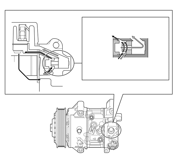
A mixture of refrigerant and cooler compressor oil flows into the oil separator chamber from the discharge chamber (*a).


ii.

The force of the refrigerant and oil mixture flow turns the oil separator cylinder, allowing the oil and refrigerant to be centrifugally separated (*b).


iii.

The separated refrigerant flows to the cooler condenser assembly through the discharge port (*c).


iv.

The separated oil circulates and lubricates the inside of the compressor with pulley assembly by flowing through the oil reservoir chamber, inlet chamber, cylinder and discharge chamber. In addition, the amount of oil that is discharged by the compressor with pulley assembly is suppressed (*d).


v.

The oil separator is installed in the refrigerant passage to separate cooler compressor oil from the refrigerant that is discharged. This helps to prevent the cooler compressor oil from flowing into the air conditioning system and reducing cooling effectiveness (*e).
Y113416
1.677,2.302 1.677,0.969 1.677,0.969 1.823,0.969 true 1.198,0.635 1.052,0.635 1.052,0.635 0.698,1.865 true 4.292,1.656 4.656,1.656 false 5.417,1.51 5.417,0.99 5.417,0.99 5.708,0.99 true 6.208,2.781 6.208,2.135 6.208,2.135 5.24,2.135 true 3.948,2.531 3.948,2.281 3.948,2.281 4.875,2.281 true 5.406,2.521 5.146,2.521 5.146,2.521 4.948,2.365 true 4.646,0.854 4.854,0.854 4.854,0.854 4.729,1.542 true 2.302,3.24 2.156,3.24 2.156,3.24 2.031,3.313 true 3.396,0.771 4.677,1.51 1.281,0.74 10 false Cooler Compressor Oil (To Oil Reservoir Chamber) 5.75,0.906 6.813,1.563 1.063,0.656 10 false Refrigerant (To Discharge Port) 3.406,1.594 4.323,2.063 0.917,0.469 10 false Oil Separator Chamber 3.427,2.531 4.656,2.948 1.229,0.417 10 false Cooler Compressor Oil 5.427,2.417 6.49,3.073 1.063,0.656 10 false Refrigerant 5.417,2.865 6.844,3.042 1.427,0.177 10 false Oil Separator Cylinder 1.24,0.552 2.76,1.021 1.521,0.469 10 false Oil Reservoir Chamber 1.854,0.875 3.406,1.344 1.552,0.469 10 false Discharge Chamber 2.354,3.156 3.271,3.521 0.917,0.365 10 false Inlet Chamber 3.104,2.396 3.333,2.656 0.229,0.26 10 false *e 4.792,3.323 5.708,3.635 0.917,0.313 10 false Oil Separator 4.375,1.344 4.604,1.604 0.229,0.26 10 false *d 4.698,1.844 4.927,2.104 0.229,0.26 10 false *b 4.771,2.396 5,2.656 0.229,0.26 10 false *a 5.417,1.76 5.646,2.021 0.229,0.26 10 false *c


d.

Variable Suction Side Throttle Operation

i.

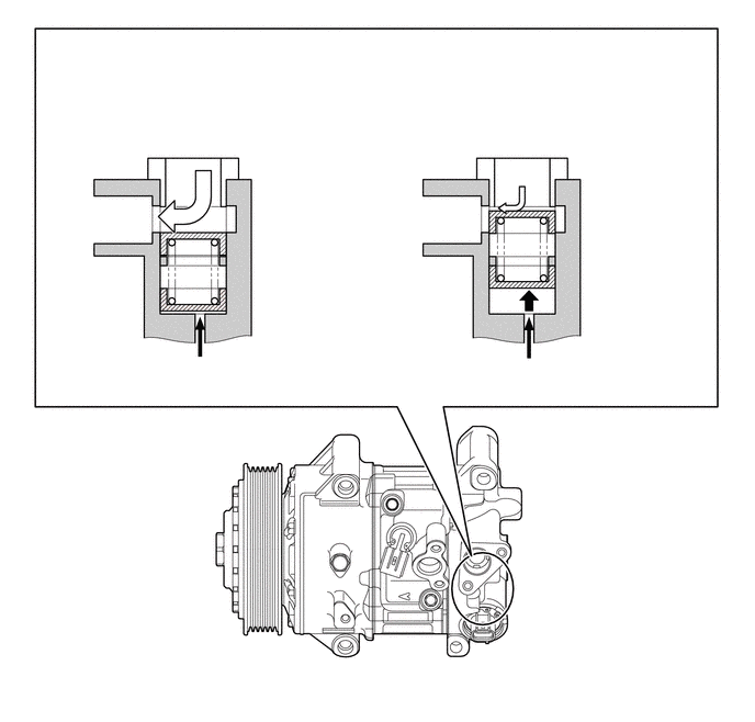
Refrigerant inlet pressure is applied to the top of the variable suction side throttle and crank chamber pressure to the bottom of the variable suction side throttle.


ii.

The pressure difference moves the variable suction side throttle up and down, expanding and contracting the refrigerant inlet passage.


iii.

When the refrigerant flow is at a maximum, the refrigerant inlet pressure is greater than the crank chamber pressure. This causes the variable suction side throttle to move down, fully opening the refrigerant inlet passage and lowering the refrigerant inlet resistance.


iv.

When the amount of refrigerant flow is controlled, the crank chamber pressure is greater than the refrigerant inlet pressure, raising the variable inlet throttle to contract the flow passage.


v.

These controls suppress noise by reducing pulsation from the refrigerant inlet.
Y113417
1.698,1.604 1.698,0.896 1.698,0.896 1.323,0.896 true 5.24,2.104 5.708,2.104 true 4.844,1.635 4.844,0.906 4.844,0.906 4.49,0.906 true 1.938,1.646 1.938,1.073 1.938,1.073 2.073,1.073 true 4.958,1.771 4.958,1.125 4.958,1.125 5.104,1.125 true 5.99,2.948 5.99,2.813 5.99,2.813 5.219,2.813 true 2.125,2.271 2.563,2.271 true 0.479,0.313 3.5,0.583 3.021,0.271 12 false With Maximum Volume of Refrigerant: 0.594,0.781 1.354,1.24 0.76,0.458 10 false Refrigerant Passage A 0.427,1.906 1.375,2.219 0.948,0.313 10 false Inlet Chamber 1.042,3.417 2.844,3.875 1.802,0.458 10 false Crank Chamber Pressure 2.604,2.01 3.448,2.823 0.844,0.813 10 false Variable Suction Side Throttle 2.125,0.979 3.656,1.448 1.531,0.469 10 false Refrigerant Flow: Large 3.76,0.802 4.49,1.271 0.729,0.469 10 false Refrigerant Passage A 5.156,1.01 6.708,1.479 1.552,0.469 10 false Refrigerant Flow: Small 3.604,1.917 4.552,2.229 0.948,0.313 10 false Inlet Chamber 4.146,3.469 6.01,3.927 1.865,0.458 10 false Crank Chamber Pressure 5.781,1.844 6.625,2.583 0.844,0.74 10 false Variable Suction Side Throttle 5.771,2.979 6.771,3.448 1,0.469 10 false Crank Pressure Inlet Chamber 3.729,0.302 6.75,0.573 3.021,0.271 12 false With Controlled Volume of Refrigerant:


e.

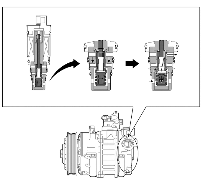
CS Valve Operation

i.

The Crank chamber to Suction passage (CS) valve, built into the solenoid valve, operates in accordance with the suction pressure. The CS valve consists of passage A and passage B.


ii.

If the vehicle is left parked for a long period, refrigerant may accumulate in the crank chamber due to the heat capacity difference.


iii.

The solenoid valve is controlled by the air conditioning amplifier assembly. While the compressor is operating, the solenoid valve pushes down the CS valve rod and open passage A (*a).


iv.

Under the above condition, only if the refrigerant accumulates in the crank chamber, the crank chamber pressure will become high. As a result, the bellows will contract because of the pressure difference with its internal pressure (vacuum), and opens passage B (*b).


v.

This causes the accumulated refrigerant to be drawn in via passage A and B, clearing the accumulated refrigerant earlier and ensuring a more immediate cooling effect.
Y113418
3.49,1.729 3.073,0.927 3.073,0.927 3.323,0.927 true 0.792,1.646 1.354,1.646 true 0.76,2.656 1.24,2.656 true 5.604,2.365 5.104,0.896 5.104,0.896 5.354,0.896 true 0.198,1.531 0.885,1.948 0.688,0.417 10 false CS Valve Rod 0.177,2.542 0.802,2.906 0.625,0.365 10 false CS Valve 6.302,1.823 6.979,2.479 0.677,0.656 10 false To Suction Passage 3.469,3.219 3.677,3.427 0.208,0.208 10 false *a 5.635,3.208 5.885,3.448 0.25,0.24 10 false *b 4.479,2.677 5.271,3.302 0.792,0.625 10 false From Crank Chamber 0.885,3.229 2.365,3.604 1.479,0.375 10 false Solenoid Valve 3.385,0.844 4.156,1.219 0.771,0.375 10 false Passage A 5.385,0.813 6.156,1.188 0.771,0.375 10 false Passage B