NM19V0EQ
_58
Vehicle Interior
_014277
HEATING / AIR CONDITIONING
_0072887
AIR CONDITIONING SYSTEM
DE
DETAILS
F
HEATING / AIR CONDITIONING AIR CONDITIONING SYSTEM DETAILS AIR CONDITIONING CONTROL
OPERATION
a.
Mode Position and Door Operation
i.
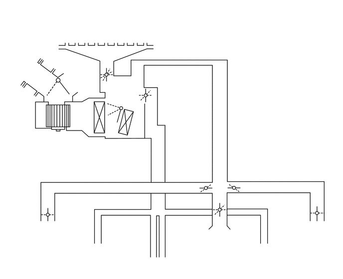
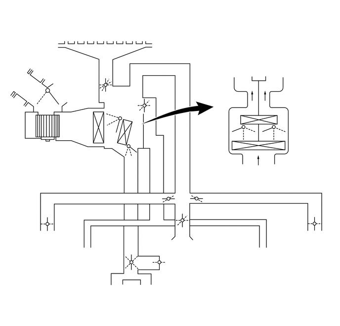
Air Conditioning Unit
1.031,2.448 1.031,2.646
false
2.042,2.74 2.042,3.083
true
2.583,2.76 2.469,3.552
2.469,3.552 2.396,3.552
true
1.75,0.563 2.865,0.771
1.115,0.208
10
false
Center Defroster
0.25,0.885 1.24,1.042
0.99,0.156
10
false
Side Defroster
3.271,0.875 4.26,1.031
0.99,0.156
10
false
Side Defroster
0.365,1.417 0.979,1.583
0.615,0.167
10
false
Fresh Air
1.365,1.552 2.052,1.729
0.688,0.177
10
false
Recirc. Air
0.885,1.677 1.031,1.885
0.146,0.208
10
false
B
1.438,1.698 1.615,1.875
0.177,0.177
10
false
A
0.146,2.781 1.583,3.198
1.438,0.417
10
false
Blower with Fan Motor Sub-assembly
1.552,3.094 2.323,3.26
0.771,0.167
10
false
Evaporator
0.219,3.448 2.5,3.677
2.281,0.229
10
false
Heater Radiator Unit Sub-assembly
2.323,2.427 2.51,2.573
0.188,0.146
10
false
C
2.219,2.24 2.385,2.448
0.167,0.208
10
false
D
2.25,2 2.417,2.198
0.167,0.198
10
false
E
2.146,1.198 2.333,1.385
0.188,0.188
10
false
F
2.24,1.271 2.375,1.448
0.135,0.177
10
false
G
2.417,1.344 2.573,1.563
0.156,0.219
10
false
H
3.052,1.646 3.229,1.823
0.177,0.177
10
false
S
2.823,2.073 3.021,2.271
0.198,0.198
10
false
R
2.76,1.896 2.927,2.063
0.167,0.167
10
false
Q
5.073,5.104 7.063,5.344
1.99,0.24
10
false
Front Footwell Register Duct
0.583,5.094 2.542,5.333
1.958,0.24
10
false
Front Footwell Register Duct
2.51,5.406 4.417,5.719
1.906,0.313
10
false
Rear Footwell Register Duct
0.656,4.656 1.573,4.906
0.917,0.25
10
false
Side Register
6.177,4.635 7.094,4.885
0.917,0.25
10
false
Side Register
3.958,4.833 5.375,4.979
1.417,0.146
10
false
Front Center Register
2.396,1.573 2.51,1.75
0.115,0.177
10
false
I
4.302,3.635 4.469,3.802
0.167,0.167
10
false
J
4.458,3.854 4.625,4.073
0.167,0.219
10
false
K
4.479,4.469 4.635,4.646
0.156,0.177
10
false
N
4.552,4.083 4.75,4.281
0.198,0.198
10
false
M
4.469,4.219 4.656,4.406
0.188,0.188
10
false
L
5.083,3.844 5.271,4.031
0.188,0.188
10
false
O
5.01,4.042 5.198,4.229
0.188,0.188
10
false
P
0.073,0.052 3.083,0.354
3.01,0.302
12
false
Models with Manual Air Conditioning:
| Control Damper | Operation Position | Door Position | Operation | |
|---|---|---|---|---|
| Air Inlet Control Damper | FRESH | A | Allows fresh air to enter. | |
| RECIRCULATION | B | Recirculates internal air. | ||
| Air Mix Control Damper | MAX COLD to MAX HOT Temperature Setting | C - D - E | Varies the mixture ratio of the fresh air and the recirculation air in order to regulate the temperature continuously from HOT to COLD. | |
| Mode Control Damper | 
|
FACE | I, K, M, O, S | Air blows out of the front center register and side register. |

|
BI-LEVEL | I, K, N, O, R | Air blows out of the front center register, side register and front and rear foot well register ducts. | |

|
FOOT | H, J, L, P, Q | Air blows out of the foot well register duct and side register. In addition, air blows out slightly from the center defroster and side defroster. | |

|
FOOT/DEF | G, J, L, P, Q | Defrosts the windshield through the center defroster, side defroster, side register, and rear register, while air is also blown out from the front and rear foot well register ducts. | |

|
DEF | F, J, L, P, S | Defrosts the windshield through the center defroster, side defroster, side register, and rear register. | |
2.063,2.979 2.063,3.229
true
0.802,2.823 0.802,3.052
true
2.531,3.01 2.417,3.781
2.417,3.781 2.344,3.781
true
0.094,0.115 3.344,0.427
3.25,0.313
12
false
Models with Automatic Air Conditioning:
1.708,0.604 2.771,0.75
1.063,0.146
10
false
Center Defroster
0.271,0.854 1.188,1.135
0.917,0.281
10
false
Side Defroster
0.052,1.625 0.677,1.792
0.625,0.167
10
false
Fresh Air
1.177,1.594 2.042,1.906
0.865,0.313
10
false
Recirculation Air
0.583,4.917 1.479,5.063
0.896,0.146
10
false
Side Register
6.25,4.917 7.115,5.063
0.865,0.146
10
false
Side Register
0.104,3.083 1.521,3.396
1.417,0.313
10
false
Blower with Fan Motor Sub-assembly
1.604,3.271 2.302,3.406
0.698,0.135
10
false
Evaporator
0.115,3.719 2.448,4.042
2.333,0.323
10
false
Heater Radiator Unit Sub-assembly
1.094,2.177 1.229,2.406
0.135,0.229
10
false
A
0.781,2.198 0.917,2.427
0.135,0.229
10
false
B
5.208,2.771 5.344,3
0.135,0.229
10
false
C
2.344,2.625 2.479,2.854
0.135,0.229
10
false
C
2.271,2.427 2.406,2.656
0.135,0.229
10
false
D
4.979,2.781 5.125,3.021
0.146,0.24
10
false
D
4.875,2.583 5.01,2.813
0.135,0.229
10
false
E
2.313,2.271 2.448,2.5
0.135,0.229
10
false
E
5.573,2.75 5.76,2.979
0.188,0.229
10
false
C'
5.802,2.792 6,3.021
0.198,0.229
10
false
D'
5.938,2.583 6.125,2.813
0.188,0.229
10
false
E'
1.833,6.063 3.688,6.208
1.854,0.146
10
false
Rear Footwell Register Duct
4.969,5.292 6.896,5.427
1.927,0.135
10
false
Front Footwell Register Duct
3.271,5.094 4.656,5.25
1.385,0.156
10
false
Front Center Register
3.385,5.646 4.792,5.813
1.406,0.167
10
false
Rear Center Register
0.5,5.292 2.354,5.438
1.854,0.146
10
false
Front Footwell Register Duct
3.25,0.865 4.177,1.146
0.927,0.281
10
false
Side Defroster
4.458,1.365 5.385,1.51
0.927,0.146
10
false
To Driver Side
5.521,1.375 7.083,1.51
1.563,0.135
10
false
To Front Passenger Side
2.156,1.469 2.292,1.698
0.135,0.229
10
false
F
2.26,1.5 2.396,1.729
0.135,0.229
10
false
G
2.385,1.615 2.521,1.844
0.135,0.229
10
false
H
3.354,4.302 3.49,4.531
0.135,0.229
10
false
J
3.719,4.104 3.854,4.333
0.135,0.229
10
false
K
3.719,4.469 3.854,4.698
0.135,0.229
10
false
L
3.781,4.323 3.917,4.552
0.135,0.229
10
false
M
3.896,4.396 4.031,4.625
0.135,0.229
10
false
N
4.302,4.104 4.438,4.333
0.135,0.229
10
false
O
4.208,4.302 4.344,4.531
0.135,0.229
10
false
P
2.771,2.146 2.906,2.375
0.135,0.229
10
false
Q
2.813,2.302 2.948,2.531
0.135,0.229
10
false
R
2.854,2.021 2.99,2.25
0.135,0.229
10
false
S
2.813,3.01 2.948,3.24
0.135,0.229
10
false
T
2.771,3.198 2.906,3.427
0.135,0.229
10
false
U
2.552,3.135 2.688,3.365
0.135,0.229
10
false
V
2.448,5.302 2.615,5.531
0.167,0.229
10
false
W
2.948,5.24 3.083,5.469
0.135,0.229
10
false
Y
2.719,5.208 2.854,5.438
0.135,0.229
10
false
X
2.313,1.813 2.448,2.042
0.135,0.229
10
false
I
| Control Damper | Operation Position | Door Position | Operation | |
|---|---|---|---|---|
| Air Inlet Control Damper | FRESH | A | Allows fresh air to enter. | |
| RECIRCULATION | B | Causes internal air to recirculate. | ||
| Air Mix Control Damper | MAX COLD to MAX HOT Temperature Setting | C - D - E
(C' - D' - E') T - U - V |
Varies the mixture ratio of the warm air and the cool air in order to regulate the temperature continuously between hot and cold. | |
| Mode Control Damper |
|
FACE | I, K, M, O, S, W | Air blows out of the front and rear center registers, and side registers. |
|
|
BI-LEVEL | I, K, N, O, R, X | Air blows out of the front and rear center registers, side register and front and rear footwell registers ducts. | |
|
|
FOOT | H, J, L, P, Q, X | Air blows out of the front and rear footwell register duct, and side registers. In addition, air blows out slightly from the center defroster and side defrosters. | |
|
|
FOOT/DEF | G, J, L, P, Q, X | Defrosts the windshield through the center defroster, side defrosters, side registers, and rear center register, while air is also blown out from the front and rear footwell register ducts. | |
|
|
DEF | F, J, L, P, S, Y | Defrosts the windshield through the center defroster, side defroster, and side registers. | |
b.
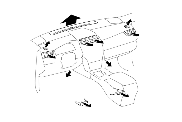
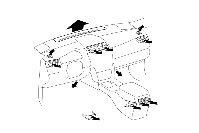
Air Outlets and Airflow Volume
Models with Manual Air Conditioning
3.688,1.854 3.833,2.021
0.146,0.167
10
false
A
5.594,1.438 5.74,1.604
0.146,0.167
10
false
B
2.25,2.333 2.396,2.5
0.146,0.167
10
false
B
2.521,3.094 2.667,3.26
0.146,0.167
10
false
C
2.99,0.406 3.135,0.573
0.146,0.167
10
false
E
1.885,1.375 2.031,1.542
0.146,0.167
10
false
F
5.167,0.531 5.313,0.698
0.146,0.167
10
false
F
3.656,4.271 3.802,4.438
0.146,0.167
10
false
D
5.063,3.875 5.208,4.042
0.146,0.167
10
false
D
4.531,2.615 4.677,2.781
0.146,0.167
10
false
C
4.146,1.75 4.292,1.917
0.146,0.167
10
false
A
| MODE | Register | Footwell | Defroster | ||||
|---|---|---|---|---|---|---|---|
| CTR | SIDE | CTR | RR | CTR | SIDE | ||
| A | B | C | D | E | F | ||
| FACE |
|

|
|

|
|
|
|
| BI-LEVEL |
|

|
|

|
|
|
|
| FOOT-F*1 |
|
|
|
|
|

|
|
| FOOT-R*2 |
|
|
|
|
|
|
|
| F/D |
|
|
|
|
|
|
|
| DEF |
|
|
|
|
|

|
|
*1: Regular foot mode (Max. HOT)
*2: Foot mode with large airflow volume from footwell rear ducts (except Max. HOT)
The size of each circle ○ indicates the ratio of airflow volume.
Models with Automatic Air Conditioning
3.688,2 3.833,2.167
0.146,0.167
10
false
A
5.594,1.583 5.74,1.75
0.146,0.167
10
false
B
2.25,2.479 2.396,2.646
0.146,0.167
10
false
B
5.719,3.792 5.865,3.958
0.146,0.167
10
false
C
5.427,3.896 5.573,4.063
0.146,0.167
10
false
C
2.521,3.229 2.667,3.396
0.146,0.167
10
false
D
2.99,0.552 3.135,0.719
0.146,0.167
10
false
F
1.885,1.521 2.031,1.688
0.146,0.167
10
false
F
5.167,0.667 5.313,0.833
0.146,0.167
10
false
F
3.656,4.417 3.802,4.583
0.146,0.167
10
false
E
5.063,4.01 5.208,4.177
0.146,0.167
10
false
E
4.531,2.75 4.677,2.917
0.146,0.167
10
false
D
4.146,1.885 4.292,2.052
0.146,0.167
10
false
A
| MODE | Selection | Register | Footwell | Defroster | ||||
|---|---|---|---|---|---|---|---|---|
| AUTO | Manual | CTR | SIDE | RR | CTR | RR | ||
| A | B | C | D | E | F | |||
| FACE | 
|
|
|
|
|
|
|
|
|
|
||||||||
| BI-LEVEL |
|
|
|
|
|
|
|
|
|
|
||||||||
| FOOT-F*1 |
|
|
|
|
|
|
|
|
|
|
||||||||
| FOOT-R*2 |
|
|
|
|
|
|
|
|
|
|
||||||||
| FOOT-D*3 |
|
|
|
|
|
|
|
|
|
|
||||||||
| FOOT/DEF |
|
|
|
|
|
|
|
|
|
|
||||||||
| DEF |
|
|
|
|
|
|
|
|
|
|
||||||||
*1: Regular foot mode
*2: Foot mode with large airflow volume from footwell rear ducts
*3: Foot mode with large airflow volume from defrosters
The size of each circle ○ indicates the ratio of airflow volume.