RM19V0EQ
_51
Engine / Hybrid System
_014573
2AR-FE ENGINE CONTROL
_0073912
CAMSHAFT OIL CONTROL VALVE
G
2AR-FE ENGINE CONTROL CAMSHAFT OIL CONTROL VALVE INSPECTION
CAUTION / NOTICE / HINT
- HINT:
-
Use the same procedure for the intake side and exhaust side.
PROCEDURE

 11101J
1.INSPECT CAMSHAFT TIMING OIL CONTROL VALVE ASSEMBLY
a.
Measure the resistance according to the value(s) in the table below.
- Standard Resistance:
Tester Connection Condition Specified Condition 1 - 2 20°C (68°F) 6.9 to 7.9 Ω
If the result is not as specified, replace the oil control valve assembly.
b.
0.781,1.438 1.115,1.906
1.115,1.906 1.229,1.906
false
2.396,0.167 2.833,0.448
0.438,0.281
10
false
*a
1.26,1.813 1.5,2.063
0.24,0.25
10
false
*1
0.448,1.771 0.719,2
0.271,0.229
10
false
*c
0.49,0.719 0.813,0.948
0.323,0.229
10
false
*b
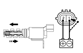
| *1 | Valve |
| *a | Component without harness connected
(Camshaft Timing Oil Control Valve) |
| *b | When applied |
| *c | When cut off |
Connect a positive (+) lead from the battery to terminal 2 and a negative (-) lead to terminal 1, and check the movement of the valve.
- OK:
Condition Specified Condition Battery voltage is applied Valve moves in left arrow direction shown in illustration Battery voltage is cut off Valve moves in right arrow direction shown in illustration
- NOTICE:
-
Confirm that the valve moves freely and does not stick in any position.
If necessary, replace the camshaft timing oil control valve assembly.
- HINT:
-
Accumulation of foreign matter can cause minor pressure leaks. Minor pressure leaks will cause the camshaft to advance or retard, and this will cause a DTC to be set.