BRAKE SYSTEM (OTHER) BRAKE BOOSTER(for LHD) INSTALLATION
PROCEDURE

 44696
1.INSTALL CHECK VALVE GROMMET
Install a new check valve grommet to the brake booster assembly.
44730
2.INSTALL BRAKE VACUUM CHECK VALVE ASSEMBLY
Install the brake vacuum check valve assembly to the brake booster assembly.
47264D
3.INSTALL BRAKE MASTER CYLINDER PUSH ROD CLEVIS
Temporarily install the lock nut and brake master cylinder push rod clevis to the brake booster assembly.
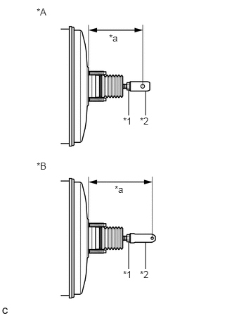
| *A | w/o VSC |
| *B | w/ VSC |
| *1 | Lock Nut |
| *2 | Brake Master Cylinder Push Rod Clevis |
| *a | Push Rod Length |
Set the push rod length as shown in the illustration.
- Push Rod Length:
Model Standard Value w/o VSC 127.5 to 128.5 mm (5.02 to 5.05 in.) w/ VSC 148.6 to 149.6 mm (5.86 to 5.88 in.)
Tighten the lock nut.
- Torque:
- 26 N*m (265 kgf*cm, 19 ft.*lbf)
44785
4.INSTALL BRAKE BOOSTER GASKET
Install a new brake booster gasket to the brake booster assembly.
44610
5.INSTALL BRAKE BOOSTER ASSEMBLY
Install the brake booster assembly to the vehicle body with the 4 nuts.
- Torque:
- 13 N*m (131 kgf*cm, 9 ft.*lbf)
- NOTICE:
-
Do not kink or damage the brake line.
47264A
6.INSTALL PUSH ROD PIN
44763A
7.INSTALL NO. 1 HOSE TO HOSE TUBE
Install the No. 1 hose to hose tube to the vehicle body with the 2 nuts.
- Torque:
- 5.4 N*m (55 kgf*cm, 48 in.*lbf)
Connect the No. 1 hose to hose tube to the brake booster assembly, and slide the clip to secure it.
47201
8.INSTALL BRAKE MASTER CYLINDER SUB-ASSEMBLY
9.INSPECT AND ADJUST BRAKE PEDAL