RM19V0EQ
_56
Audio / Visual / Telematics
_014599
AUDIO / VIDEO
_0074081
AUDIO AND VISUAL SYSTEM(for Radio and Display Type)
J
AUDIO / VIDEO AUDIO AND VISUAL SYSTEM(for Radio and Display Type) Parking Brake Switch Circuit
DESCRIPTION
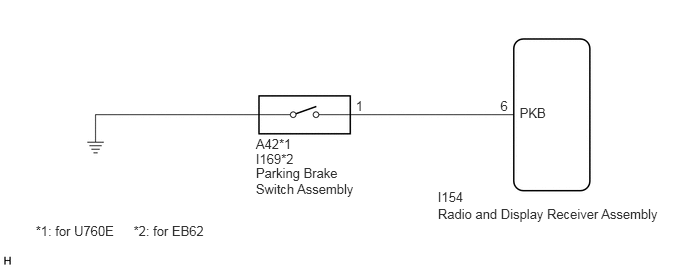
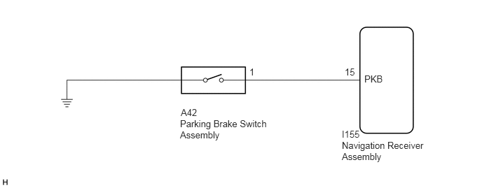
This circuit is from the parking brake switch assembly to the radio and display receiver assembly.
WIRING DIAGRAM
for RHD before Oct. 2014, for LHD
3.706,1.017 3.835,1.184
0.129,0.167
10
1
5.213,1.017 5.342,1.184
0.129,0.167
10
6
4.56,1.973 4.878,2.14
0.318,0.167
10
I154
4.561,2.142 6.948,2.293
2.387,0.151
10
Radio and Display Receiver Assembly
2.665,1.417 3.171,1.584
0.506,0.167
10
A42*1
2.665,1.568 3.171,1.734
0.506,0.167
10
I169*2
0.372,2.318 1.262,2.485
0.89,0.167
10
*1: for U760E
1.391,2.318 2.188,2.485
0.797,0.167
10
*2: for EB62
2.665,1.718 3.794,2.099
1.129,0.381
10
Parking Brake Switch Assembly
5.412,1.099 5.766,1.28
0.354,0.181
10
PKB
for RHD from Oct. 2014
2.677,1.76 4.01,2.208
1.333,0.448
10
false
Parking Brake Switch Assembly
3.708,0.99 4.167,1.188
0.458,0.198
10
false
1
5.125,0.99 5.583,1.188
0.458,0.198
10
false
15
5.417,1.094 5.875,1.292
0.458,0.198
10
false
PKB
5.083,1.917 5.542,2.115
0.458,0.198
10
false
I155
5.083,2.083 6.302,2.583
1.219,0.5
10
false
Navigation Receiver Assembly
2.688,1.594 3.146,1.792
0.458,0.198
10
false
A42
PROCEDURE
1.CHECK BRAKE WARNING LIGHT
a.
Check that the brake warning light comes on when the parking brake is applied and goes off when it is released.
- OK:
The brake warning light operates as specified above.
- Result:
Proceed to OK NG
OK
2.CHECK HARNESS AND CONNECTOR (PARKING BRAKE SWITCH ASSEMBLY - RADIO AND DISPLAY RECEIVER ASSEMBLY)
NG
GO TO BRAKE CONTROL / DYNAMIC CONTROL SYSTEMS
2.CHECK HARNESS AND CONNECTOR (PARKING BRAKE SWITCH ASSEMBLY - RADIO AND DISPLAY RECEIVER ASSEMBLY)
a.
Disconnect the radio and display receiver assembly connector.
b.
Disconnect the parking brake switch assembly connector.
c.
Measure the resistance according to the value(s) in the table below. (for RHD before Oct.2014, for LHD)
- Standard Resistance:
for U760E Tester Connection Condition Specified Condition I154-6 (PKB) - A42-1 Always Below 1 Ω I154-6 (PKB) - Body ground Always 10 kΩ or higher
for EB62 Tester Connection Condition Specified Condition I154-6 (PKB) - I169-1 Always Below 1 Ω I154-6 (PKB) - Body ground Always 10 kΩ or higher
d.
Measure the resistance according to the value(s) in the table below. (for RHD from Oct. 2014)
- Standard Resistance:
Tester Connection Condition Specified Condition I154-6 (PKB) - I169-1 Always Below 1 Ω I154-6 (PKB) - Body ground Always 10 kΩ or higher
- Result:
Proceed to OK NG
OK
PROCEED TO NEXT SUSPECTED AREA SHOWN IN PROBLEM SYMPTOMS TABLE
NG
REPAIR OR REPLACE HARNESS OR CONNECTOR