THEFT DETERRENT / KEYLESS ENTRY ENGINE IMMOBILISER SYSTEM(w/o Smart Entry and Start System) Door Courtesy Switch Circuit
DESCRIPTION
When an additional transponder key is registered, the transponder key ECU assembly detects the front door courtesy light switch assembly (for driver door) open/close condition, and enters the key registration mode.
WIRING DIAGRAM
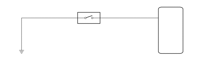
CAUTION / NOTICE / HINT
- NOTICE:
-
If the transponder key ECU assembly is replaced, refer to Service Bulletin.
PROCEDURE
Connect the intelligent tester to the DLC3.
Turn the ignition switch to ON.
Turn the intelligent tester on.
Enter the following menus: Body / Immobiliser / Data List.
Read the Data List according to the display on the intelligent tester.
- Body Electrical > Immobiliser > Data List
-
Tester Display Measurement Item Range Normal Condition Diagnostic Note D Door Courtesy SW Driver door courtesy light switch signal ON or OFF ON: Driver door open
OFF: Driver door closed-
- Body Electrical > Immobiliser > Data List
-
Tester Display D Door Courtesy SW - 50003 260 4
- OK:
On the intelligent tester screen, the item changes between ON and OFF according to the chart above.
- Result:
Proceed to OK NG
OK
NG
Disconnect the transponder key ECU assembly connector.
Measure the resistance according to the value(s) in the table below.
- Standard Resistance:
Tester Connection Switch Condition Specified Condition3 I19-7 (CTY) - Body ground Courtesy switch pushed
(Door closed)10 kΩ or higher I19-7 (CTY) - Body ground Courtesy switch free
(Door open)Below 1 Ω
- Result:
Proceed to OK NG
OK
NG
Remove the front door courtesy light switch assembly (for driver door).
Click hereVehicle Interior>LIGHTING (INT)>FRONT DOOR COURTESY SWITCH>REMOVAL
Measure the resistance according to the value(s) in the table below.
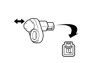
| *1 | Switch Body |
| *a | Component without harness connected
(Front Door Courtesy Light Switch Assembly (for Driver Door)) |
- Standard Resistance:
Tester Connection Switch Condition Specified Condition3 1 - Switch body Courtesy switch pushed
(Door closed)10 kΩ or higher 1 - Switch body Courtesy switch not pushed
(Door open)Below 1 Ω
- Result:
Proceed to OK NG
OK
NG